Review
. 2022 Feb;9(5):e2103965.
doi: 10.1002/advs.202103965. Epub 2021 Dec 19.

Spider Silk-Inspired Artificial Fibers

Affiliations
Review

Spider Silk-Inspired Artificial Fibers

Jiatian Li et al. Adv Sci (Weinh). 2022 Feb.

Abstract

Spider silk is a natural polymeric fiber with high tensile strength, toughness, and has distinct thermal, optical, and biocompatible properties. The mechanical properties of spider silk are ascribed to its hierarchical structure, including primary and secondary structures of the spidroins (spider silk proteins), the nanofibril, the "core-shell", and the "nano-fishnet" structures. In addition, spider silk also exhibits remarkable properties regarding humidity/water response, water collection, light transmission, thermal conductance, and shape-memory effect. This motivates researchers to prepare artificial functional fibers mimicking spider silk. In this review, the authors summarize the study of the structure and properties of natural spider silk, and the biomimetic preparation of artificial fibers from different types of molecules and polymers by taking some examples of artificial fibers exhibiting these interesting properties. In conclusion, biomimetic studies have yielded several noteworthy findings in artificial fibers with different functions, and this review aims to provide indications for biomimetic studies of functional fibers that approach and exceed the properties of natural spider silk.

Keywords: biomimetics; hydrogel fiber; recombinant spider silk; spider silk; strong and tough fibers.


Conflict of interest statement

The authors declare no conflict of interest.

Figures
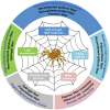
Figure 1
Figure 1
Properties of spider silk and the inspired artificial fibers. The spider drawing is adapted from http://cliparts.co/vector‐spider‐web.
Figure 2
Figure 2
a) Schematic structure of MA spidroins including repetitive amino acid motifs and the corresponding secondary structures. Reproduced with permission.[ 51 ] Copyright 2015, Springer Nature. b) Schematic illustration of the hierarchical structure of the spider silk. Reproduced with permission.[ 91 ] Copyright 2021, Wiley‐VCH. c) Both the silkworm silk and the spider dragline silk are composed of interlocking nanofibrils, where β‐crystallites are connected by the amorphous chains and form a network. Reproduced with permission.[ 30 ] Copyright 2014, Royal Society of Chemistry. d) The schematic “fishing‐net” structure of the spider silk. The β‐crystals are formed by layer‐by‐layer stacking of the β‐sheets on the initial β‐sheet, which are formed by folding of the repetitive protein molecular chains serving as a crystal nucleation seed. Reproduced with permission.[ 35 ] Copyright 2016, Wiley‐VCH. e) The multilayer structure of the spider dragline silk. Reproduced under the terms of the Creative Commons Attribution License.[ 38 ] Copyright 2007, The Authors. Published by PLOS.
Figure 3
Figure 3
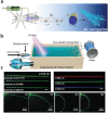
a) Schematic microfluidic spinning of the recombinant spider silk fiber. Reproduced under the terms of the Creative Commons CC BY license.[ 58 ] Copyright 2016, Springer Nature. b) Schematic of the RSF/CNF fibers by dry‐spinning using a microfluidic channel. Reproduced with permission.[ 75a ] Copyright 2019, American Chemical Society. c) Proposed model of the nano‐confined crystallite toughening mechanism of hybrid artificial silks. Reproduced with permission.[ 75b ] Copyright 2014, Royal Society of Chemistry. d) Fabrication of the pseudoprotein polymer fiber. Reproduced with permission.[ 81 ] Copyright 2019, Wiley‐VCH.
Figure 4
Figure 4
a) Synthesis of polyacrylic acid hydrogel by free radical polymerization employing acrylic acid as the monomer, ammonium persulfate (APS) as the initiator, and vinyl‐functionalized silica nanoparticles as the cross‐linker. b) A single fiber being draw‐spun by dipping a steel rod into the hydrogel reservoir. The hydrogel fiber shown in the micrograph contained 0.1 wt% VSNPs. Scale bar: 10 µm. Reproduced under the terms of the Creative Commons CC BY license.[ 83 ] Copyright 2019, Springer Nature. c) A polymer fiber being draw‐spun from a bulk hydrogel precursor composed of bionic acid‐terminated PEGs and HA, which formed non‐covalent dynamic interactions. Reproduced with permission.[ 84 ] Copyright 2020, American Chemical Society. d) Schematic illustration of the preparation process and network microstructure of the PVA/Alg/HAP hybrid macrofiber. Reproduced with permission.[ 88 ] Copyright 2019, Wiley‐VCH. e) Schematic illustration of the fabrication process of the bioinspired hierarchical helical BC–Alg macrofibers. At each structural level, every two sub‐level gel filaments are twisted together to prepare a higher‐level helical fiber. Helical‐2, 4, and 8 indicate helical fibers composed of 2, 4, and 8 original filaments, respectively. The helical fibers with the same twist direction (Albert lay) at each level are defined as helical (+). The helical fibers with opposite twist directions (interactive lay) at each level are defined as helical (−). Reproduced under the terms of the Creative Commons CC BY license.[ 93 ] Copyright 2019, Oxford University Press.
Figure 5
Figure 5
a) Lifting of an object by spider dragline silk during moisture‐driven supercontraction and cyclical lifting of the objects by periodically changing the humidity. Reproduced with permission.[ 99 ] Copyright 2009, Company of Biologists Ltd. b) Force–displacement relationship during coiling of a spider capture silk in water droplets by stress relaxation, which showed a behavior of solid–liquid transition. Reproduced with permission.[ 100 ] Copyright 2016, National Academy of Sciences (United States). c) Schematic illustration of the hydrogel consisting of P1 grafted onto the silica nanoparticles, P2, cucurbit[8]uril, which exhibited a double‐crosslinked network, including the physical interactions (between P1 and P2) and covalent crosslinks in P2 (formed by an additional UV‐crosslinking step). Reproduced under the terms of the Creative Commons CC BY License.[ 106 ] Copyright 2018, Wiley‐VCH. d) Snapshots of a 5‐cm‐long hydrogel fiber supercontracted into a 50‐µm‐diameter ball at 95% RH. Scale bar: 1 cm. The white dashed lines indicate the supercontraction process of hydrogel fibers, and the white dashed oval presents the hydrogel small ball. Reproduced under the terms of the Creative Commons CC BY license.[ 83 ] Copyright 2019, Springer Nature.
Figure 6
Figure 6
a) Environmental SEM images of the periodic spindle‐knots linking with slender joints of the spider silk. The apex angle of the spindle‐knots (2β) is about 19°. b) Low‐ and c) high‐magnification images showing that the spindle‐knot is randomly interweaved by nanofibrils. d) Low‐ and e) high‐magnification images of the joint, which is composed of axially aligned nanofibrils. f) Small water droplets condensing on the spider silk (denoted 1–10). The water droplets move directionally from the joints to the spindle‐knots (as indicated by arrows) and increase in volume. g) The smaller water droplets (1–5) coalesce to a larger water droplet, while the water droplets (6, 7, and 8–10) coalesce to two medium water droplets. Reproduced with permission.[ 108 ] Copyright 2010, Springer Nature. h) Scheme of fabricating artificial fibers with spindle‐knot structure. Reproduced with permission.[ 110 ] Copyright 2011, Wiley‐VCH. i) Schematic illustration of the fluid coating method used for large‐scale fabrication of artificial fibers with spindle‐knot structure. Reproduced with permission.[ 112 ] Copyright 2011, Wiley‐VCH. j) An all silk‐protein fiber consisting of B. mori degummed silk coated with recombinant MaSp2. The spindle‐knot structure was generated by coating a thin layer of MaSp2 by drawing the fiber out of the dope, which subsequently split up into knots with periodic intervals. Reproduced with permission.[ 116 ] Copyright 2020, Wiley‐VCH.
Figure 7
Figure 7
a) Schematic diagram for preparation of light waveguide fibers by wet‐spinning employing a microfluidic chip. Reproduced with permission.[ 119 ] Copyright 2021, Elsevier. b) Schematic illustration of the integrated dynamic wet‐spinning apparatus. c) Light transmission within hydrogel fiber with different fiber diameters and different laser wavelengths (scale bar: 1 cm), and photographs of light propagation through the hydrogel fiber with different bending angles. Reproduced under the terms of the Creative Commons CC BY License.[ 85a ] Copyright 2020, Oxford University Press.

References

    1. Agnarsson I., Kuntner M., Blackledge T. A., PLoS One 2010, 5, e11234. - PMC - PubMed
    1. a) Hinman M. B., Lewis R. V., J. Biol. Chem. 1992, 267, 19320; - PubMed
    2. b) Omenetto F. G., Kaplan D. L., Science 2010, 329, 528. - PMC - PubMed
    1. Huang X., Liu G., Wang X., Adv. Mater. 2012, 24, 1482. - PubMed
    1. a) Liu Y., Shao Z., Vollrath F., Nat. Mater. 2005, 4, 901; - PubMed
    2. b) Bell F. I., McEwen I. J., Viney C., Nature 2002, 416, 37. - PubMed
    1. Liu D., Yu L., He Y., Peng K., Liu J., Guan J., Dunstan D. J., Appl. Phys. Lett. 2017, 111, 013701.

Publication types

LinkOut - more resources