Review
. 2021 Dec 15;8(12):3394-3405.
doi: 10.1021/acsphotonics.1c00951. Epub 2021 Nov 17.

Shaping of Electron Beams Using Sculpted Thin Films

Affiliations
Review

Shaping of Electron Beams Using Sculpted Thin Films

Dolev Roitman et al. ACS Photonics. .

Abstract

Electron beam shaping by sculpted thin films relies on electron-matter interactions and the wave nature of electrons. It can be used to study physical phenomena of special electron beams and to develop technological applications in electron microscopy that offer new and improved measurement techniques and increased resolution in different imaging modes. In this Perspective, we review recent applications of sculpted thin films for electron orbital angular momentum sorting, improvements in phase contrast transmission electron microscopy, and aberration correction. For the latter, we also present new results of our work toward correction of the spherical aberration of Lorentz scanning transmission electron microscopes and suggest a method to correct chromatic aberration using thin films. This review provides practical insight for researchers in the field and motivates future progress in electron microscopy.


Conflict of interest statement

The authors declare no competing financial interest.

Figures
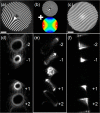
Figure 1
Figure 1
Selected examples of electron beam shaping masks and measurements. (a) Fork mask generating vortex beams with an OAM of 10ℏ. (b) As for part a, using the microscope stigmator to apply a transformation to a Hermite–Gauss-like beam. The colored circle depicts the magnetic field distribution of a quadrupole lens, acting as a stigmator. (c) Off-axis Airy mask. (d) Measurement of part a in a diffraction plane, showing vortex beams around the central, transmitted beam (mechanically blocked to protect the camera). (e) As for part d, after engaging the TEM’s built-in stigmators. In a diffraction plane, the Laguerre–Gauss vortex approximations have transformed into a Hermite–Gauss-like intensity pattern of order 10, as evidenced by counting the dark lines. (f) Airy beams measured in the diffraction plane, resulting from the mask in part c. The scale bars in part a–c are 2 μm. The diameter of the masks is 10 μm.
Figure 2
Figure 2
Principle of operation of an OAM sorter. (a–c) SEM images of the generator, transformation, and corrector holograms. Taken from ref (60).
Figure 3
Figure 3
Images of a lacey carbon film recorded using (A) a ZPP and (C) a VPP. The image in part B is a fringe-reduced software-filtered version of the ZPP image in part A. Scale bar: 20 nm. Taken from ref (66).
Figure 4
Figure 4
Structured illumination for phase contrast STEM. (a–d) MIDI-STEM. (a) Example CBED pattern consisting of alternating constructive and destructive interference. (b) SEM image of the patterned Fresnel zone plate. (c, d) Virtual MIDI-STEM and ADF images of Au nanoparticles on a carbon support, processed from the 4D-STEM data set. Taken from ref (75). (e, f) STEM holography. (e) Schematic diagram of the optical setup, which involves the use of a diffraction grating in a condenser aperture position. (f) Reconstructed phase image of Au nanoparticles on a thin carbon support. Taken from ref (80). (g–i) Near-field electron ptychography. (g) An example near-field diffraction pattern. (h) Reconstructed phase image of the diffuser. (i, j) Reconstructed amplitude and phase image of the latex sphere on carbon/Au nanoparticle substrate, processed from only nine diffraction patterns. Adapted from ref (90).
Figure 5
Figure 5
(a, c) Images of fabricated correctors and (b, d) corresponding designed radial thickness profiles. (a, b) Fractured corrector of diameter 50 μm for the conventional high-resolution STEM mode with Λ = 2 and t2pi = 69 nm. (c, d) Continuous corrector of diameter 150 μm for the Lorentz STEM mode with Λ = 1.05 and t2pi = 77 nm. (e) A comparison between low-magnification STEM images of the Au waffle grid using a 150 μm aperture and the corrector mask shown in part c. Both were taken at α = 1.3 mrad. One can see many more details on the Au surface with the corrector.
Figure 6
Figure 6
Schematic illustrations of the chromatic abserration of (a) an electron magnetic lens and (b) an electron diffractive lens fractured design. rm is the radius of the mth concentric annular section. The peak-to-valley thickness, t2π, introduces a 2π phase shift to the electron beam. Different rays’ colors represent the wavelength spread of the electron beam. (a) Longer wavelengths have a larger focal length. (b) The thin film lens is designed to have the opposite chromatic aberration. Combined together, the diffractive lens’ negative chromatic aberration cancels the aberration of the magnetic lens.

References

    1. Haider M.; Rose H.; Uhlemann S.; Schwan E.; Kabius B.; Urban K. A Spherical-Aberration-Corrected 200 KV Transmission Electron Microscope. Ultramicroscopy 1998, 75, 53.10.1016/S0304-3991(98)00048-5. - DOI
    1. Kabius B.; Hartel P.; Haider M.; Müller H.; Uhlemann S.; Loebau U.; Zach J.; Rose H. First Application of Cc-Corrected Imaging for High-Resolution and Energy-Filtered TEM. J. Electron Microsc. 2009, 58 (3), 147–155. 10.1093/jmicro/dfp021. - DOI - PubMed
    1. Verbeeck J.; Tian H.; Schattschneider P. Production and Application of Electron Vortex Beams. Nature 2010, 467 (7313), 301–304. 10.1038/nature09366. - DOI - PubMed
    1. McMorran B. J.; Agrawal A.; Anderson I. M.; Herzing A. A.; Lezec H. J.; McClelland J. J.; Unguris J. Electron Vortex Beams with High Quanta of Orbital Angular Momentum. Science (Washington, DC, U. S.) 2011, 331 (6014), 192–195. 10.1126/science.1198804. - DOI - PubMed
    1. Voloch-Bloch N.; Lereah Y.; Lilach Y.; Gover A.; Arie A. Generation of Electron Airy Beams. Nature 2013, 494 (7437), 331–335. 10.1038/nature11840. - DOI - PubMed