Review
. 2021 Dec 8;11(12):3335.
doi: 10.3390/nano11123335.

Research Progress of Photo-/Electro-Driven Thermochromic Smart Windows

Affiliations
Review

Research Progress of Photo-/Electro-Driven Thermochromic Smart Windows

Xiaotong Zou et al. Nanomaterials (Basel). .

Abstract

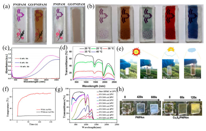
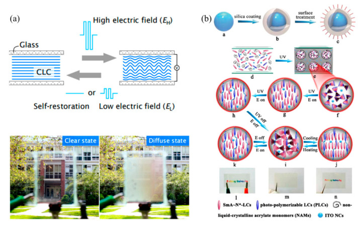
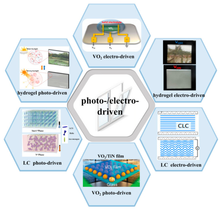
Thermochromic smart windows can automatically control solar radiation according to the ambient temperature. Compared with photochromic and electrochromic smart windows, they have a stronger applicability and lower energy consumption, and have a wide range of application prospects in the field of building energy efficiency. At present, aiming at the challenge of the high transition temperature of thermochromic smart windows, a large amount of innovative research has been carried out via the principle that thermochromic materials can be driven to change their optical performance by photothermal or electrothermal effects at room temperature. Based on this, the research progress of photo- and electro-driven thermochromic smart windows is summarized from VO2-based composites, hydrogels and liquid crystals, and it is pointed out that there are two main development trends of photo-/electro-driven thermochromic smart windows. One is exploring the diversified combination methods of photothermal materials and thermochromic materials, and the other is developing low-cost large-area heating electrodes.

Keywords: photo-/electro-driven; research progress; smart windows; thermochromic.


Conflict of interest statement

The authors declare no conflict of interest.

Figures

Figure 3
Figure 3
(a) Photos of the transparency/opacity transition of PNIPAm glass and GO/PNIPAm glass before and after 5 min of sunlight. Reproduced with permission from [25]. Copyright 2017, Elsevier. (b) Color GO/PNIPAm glass. Reproduced with permission from [25]. Copyright 2017, Elsevier. (c) Ultraviolet–visible–near infrared absorption spectra of 0.025 wt% SnO2 with Sb doping content of 0, 5 and 10%. Reproduced with permission from [27]. Copyright 2017, American Chemical Society. (d) Transmission spectra of 5HATO films at different temperatures. Reproduced with permission from [28]. Copyright 2018, Elsevier. (e) PTCSWs prototype and pure HPMC in the hot summer (left), digital photos of soft sunny summer days (middle) and cloudy days (right). Reproduced with permission from [31]. Copyright 2018, Elsevier. (f) Temperature rise trajectory of PVA/dye film with or without AuNRs. Reproduced with permission from [31]. Copyright 2018, Elsevier. (g) UV-Vis-NIR spectra of PTCSWs prototype. Reproduced with permission from [31]. Copyright 2018, Elsevier. (h) Photos of Cu7S4/PNIPAm and PNIPAm hydrogels under real sunlight in summer (31 °C). Reproduced with permission from [32]. Copyright 2019, Elsevier.
Figure 5
Figure 5
(a) The preparation process diagram of VO2NF/AgNWS electrochromic film on glass substrate. Reproduced with permission from [39]. Copyright 2014, Royal Society of Chemistry. (b) Transmission spectra of VO2NF/AgNWS electrochromic films under different applied voltages. Reproduced with permission from [39]. Copyright 2014, Royal Society of Chemistry. (c) VO2/AZO multilayer structure, AZO at the bottom and edge diagram. Reproduced with permission from [44]. Copyright 2020, Springer Nature. (d) CNT-VO2-MICA film preparation process schematic diagram. Reproduced with permission from [45]. Copyright 2017, Elsevier. (e) Gate control diagram of VO2 device with source, drain and gate. Reproduced with permission from [46]. Copyright 2019, The American Association for the Advancement of Science. (f) Optical transmission spectra of VO2, HxVO2 and HVO2 films. Reproduced with permission from [46]. Copyright 2019, The American Association for the Advancement of Science.
Figure 7
Figure 7
(a) Schematic diagram and photo of CLC smart window (d ≈ 45 μm). Reproduced with permission from [58]. Copyright 2018, Optica. (b) Schematic diagram of preparation and response of ITOncs/liquid crystal. (ac): a single ITO NC is encapsulated with a hydrophilic silicon barrier to form a core/shell structure, and then subjected to methacryloylpropyl-trimethoxysilane (MPTMS) surface treatment; (dk): Preparation procedures for the smart film: a homogenous polymeric syrup is sandwiched between two plastic transparent substrates (d), and the film is irradiated with ultraviolet light to form a porous polymer network and LCs droplets (e,f). Then, an electric field is applied to perpendicularly orient the LCs (g), meantime, a second step of UV polymerization is carry out to complete the cross-linking between PLCs in the LCs droplets to form orientated liquid-crystalline polymer networks in the porous structure (h). According to temperature or electric field, the original film (l) can be reversibly changed between transparent (n) and opaque (m). Reproduced with permission from [60]. Copyright 2017, Royal Society of Chemistry.
Figure 1
Figure 1
Types and working principle of photo- and electro-driven thermochromic smart windows.
Figure 2
Figure 2
(a) Schematic diagram of VO2/TiN smart windows. (b) UV-Vis spectra of TiOx (0 h), TiOxNy (2 h), TiN (10 h) nanoarrays on quartz substrate. (c) Transmission spectra of VO2/TiN coatings at 20 °C and 80 °C. Reproduced with permission from [21]. Copyright 2018, Wiley.
Figure 4
Figure 4
(a) Self-occlusion shutter schematic and POM images [36]. (b) Preparation process of polymer-stabilized liquid crystal (PSLC) smart window. Reproduced with permission from [37]. Copyright 2017, American Chemical Society.
Figure 6
Figure 6
(a) Ag mesh electrode square and honeycomb arrays. Reproduced with permission from [52]. Copyright 2016, Wiley. (b) Sunlight transmittance of conventional and honeycomb arrays [52]. (c) Schematic diagram of the manufacturing steps of Sn/hydrogel devices. Reproduced with permission from [53]. Copyright 2017, Elsevier. (d) Cu/HPMC hydrogel before and after Joule heating [53]. Reproduced with permission from [53]. Copyright 2017, Royal Society of Chemistry.

References

    1. Pérez-Lombard L., Ortiz J., Pout C. A review on buildings energy consumption information. Energy Build. 2008;40:394–398. doi: 10.1016/j.enbuild.2007.03.007. - DOI
    1. Svensson J., Granqvist C.G. Electrochromic coatings for smart windows: Crystalline and amorphous WO3 films. Thin Solid Films. 1985;126:31–36. doi: 10.1016/0040-6090(85)90171-3. - DOI
    1. Ji H., Liu D., Cheng H., Zhang C. Inkjet printing of vanadium dioxide nanoparticles for smart windows. J. Mater. Chem. C. 2018;6:2424–2429. doi: 10.1039/C8TC00286J. - DOI
    1. Cui Y., Ke Y., Liu C., Chen Z., Wang N., Zhang L., Zhou Y., Wang S., Gao Y., Long Y. Thermochromic VO2 for energy-efficient smart windows. Joule. 2018;6:1707–1746. doi: 10.1016/j.joule.2018.06.018. - DOI
    1. Ji H., Liu D., Cheng H., Tao Y. Large area infrared thermochromic VO2 nanoparticle films prepared by inkjet printing technology. Sol. Energy Mater. Sol. Cells. 2019;194:235–243. doi: 10.1016/j.solmat.2019.02.028. - DOI

LinkOut - more resources