Review
. 2021 Dec;7(12):1628-1644.
doi: 10.1016/j.jacep.2021.09.008. Epub 2021 Nov 24.

Living Anatomy of the Pericardial Space: A Guide for Imaging and Interventions

Affiliations
Review

Living Anatomy of the Pericardial Space: A Guide for Imaging and Interventions

Shumpei Mori et al. JACC Clin Electrophysiol. 2021 Dec.

Abstract

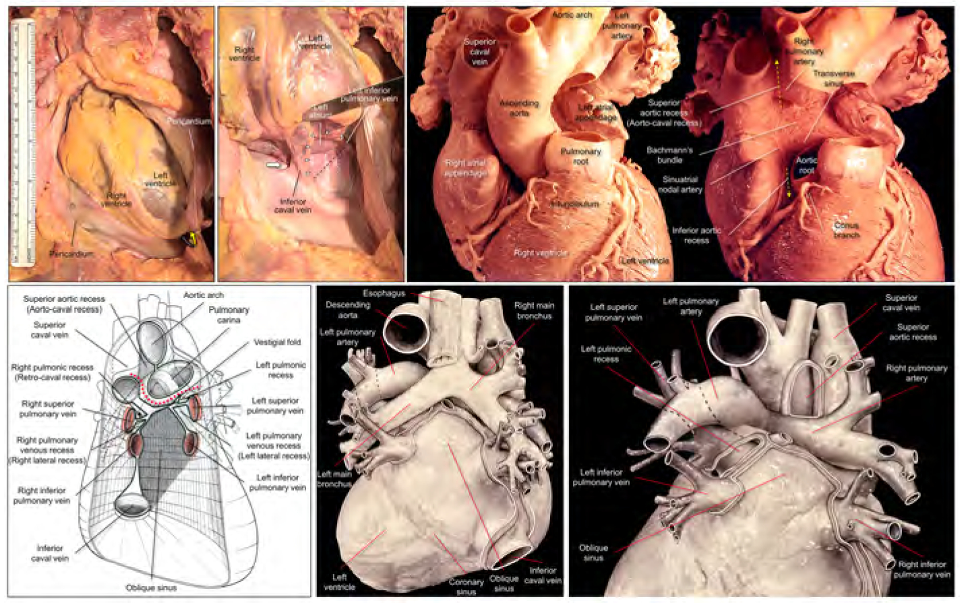
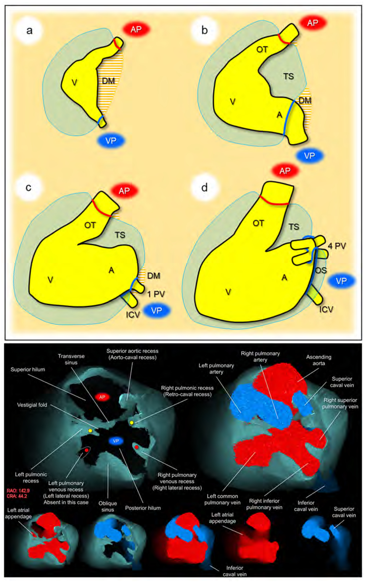
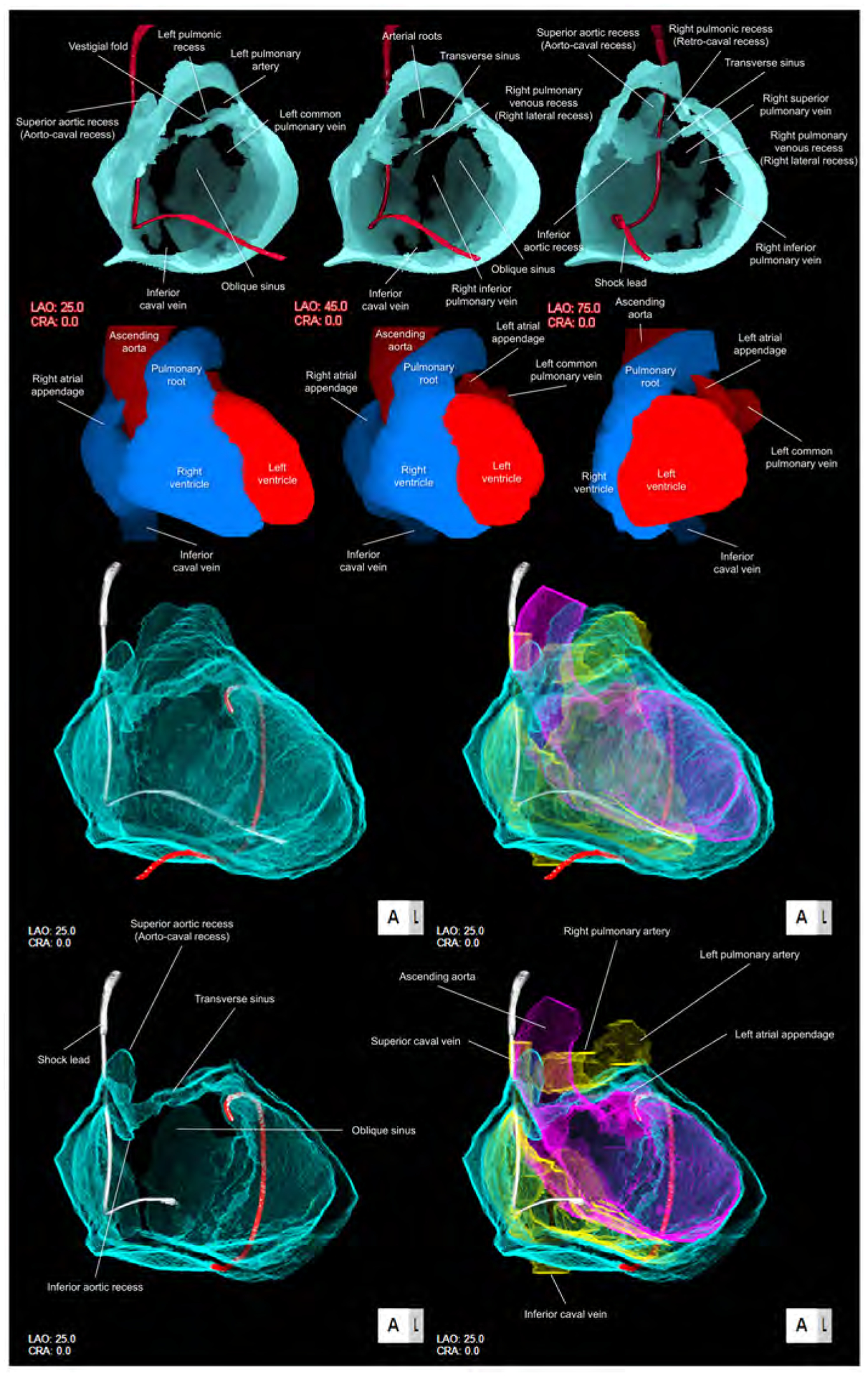
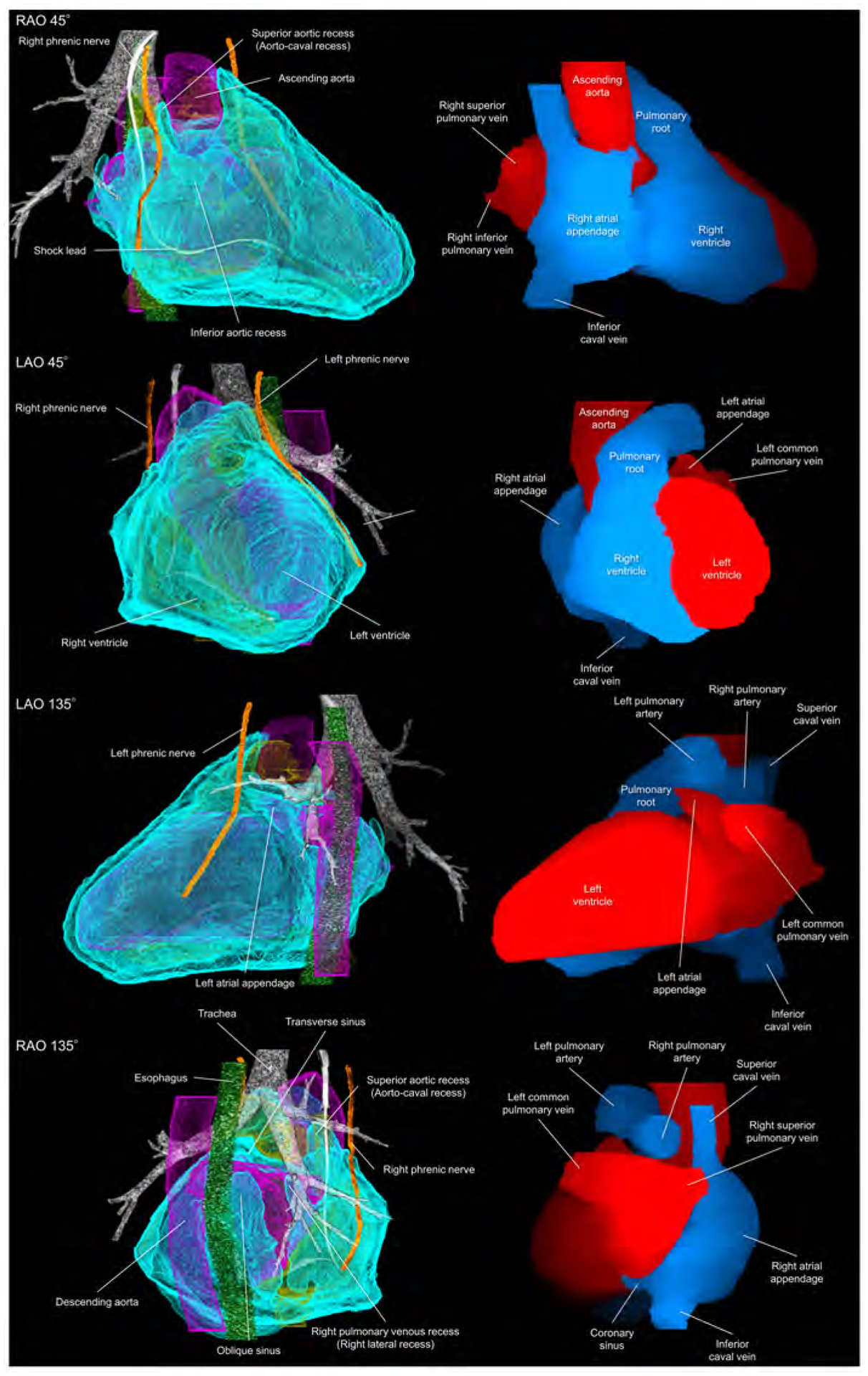
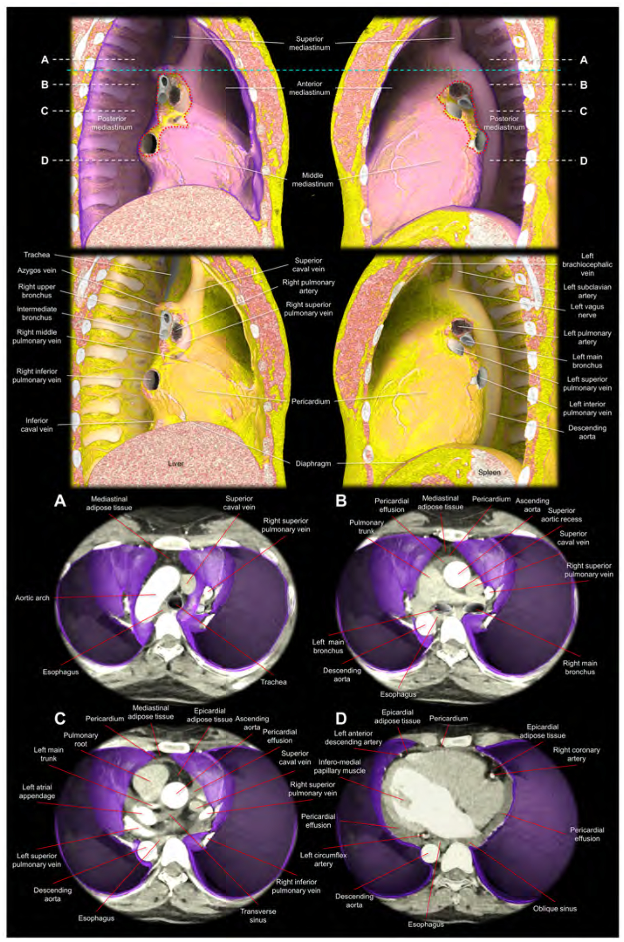
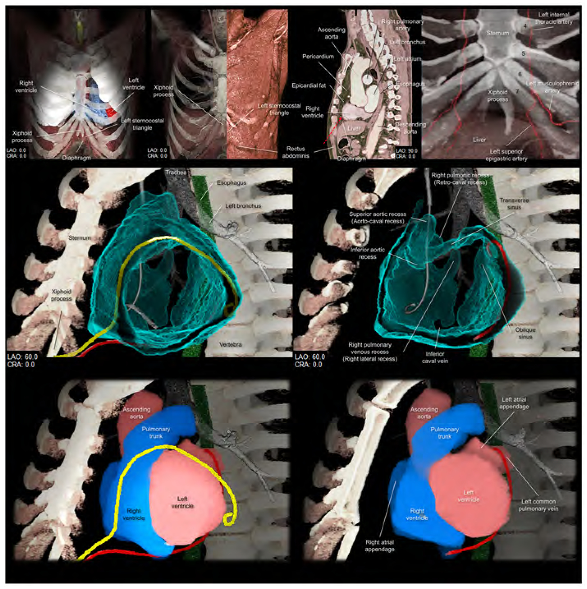
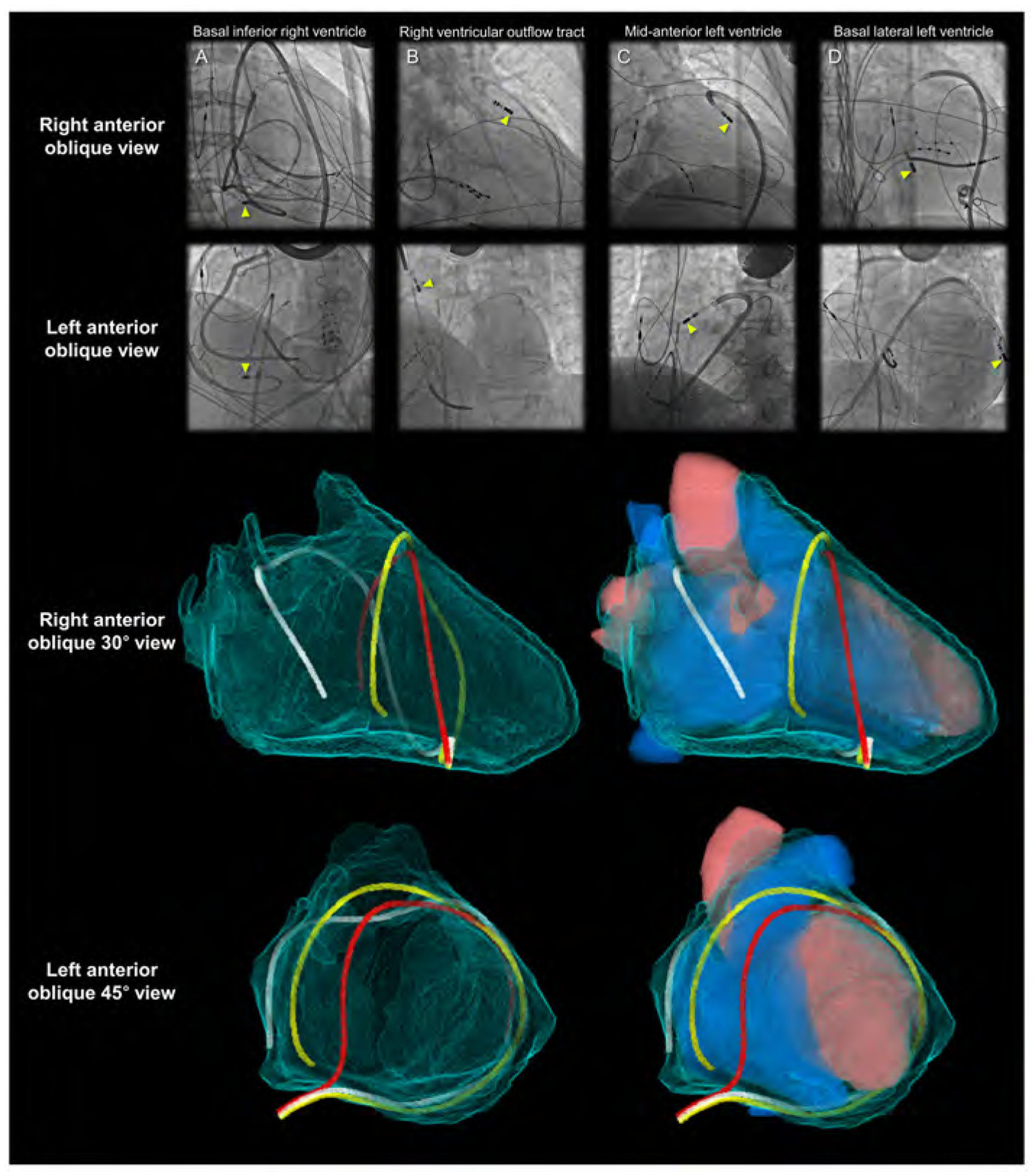
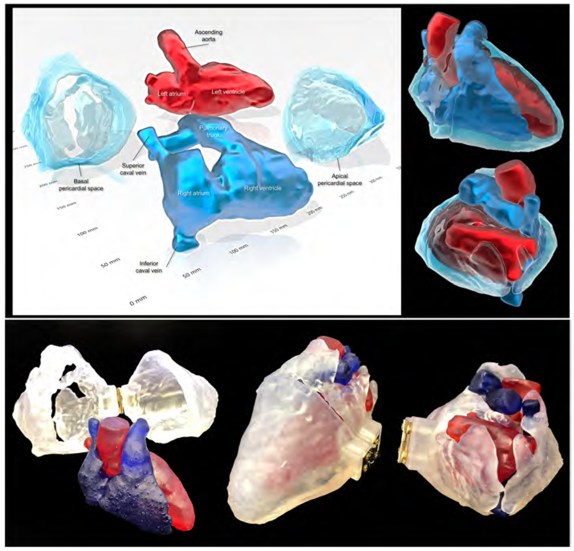
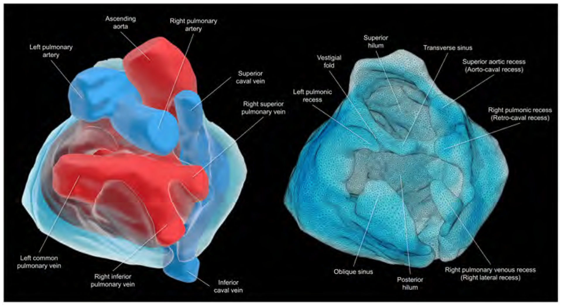
The pericardium of the human heart has received increased attention in recent times due to interest in the epicardial approach for cardiac interventions to treat cardiac arrhythmias refractory to conventional endocardial approaches. To support further clinical application of this technique, it is fundamental to appreciate the living anatomy of the pericardial space, as well as its relationships to the surrounding structures. The anatomy of the pericardial space, however, is extremely difficult regions to visualize. This is due to its complex 3-dimensionality, and the "potential" nature of the space, which becomes obvious only when there is collection of pericardial fluid. This potential space, which is bounded by the epicardium and pericardium, can now be visualized by special techniques as we now report, permitting appreciation of its living morphology. Current sources of knowledge are limited to the dissection images, surgical images, and/or illustrations, which are not necessarily precise or sufficient to provide relevant comprehensive anatomical knowledge to those undertaking the epicardial approach. The authors demonstrate, for the first time to their knowledge, the 3-dimensional living anatomy of the pericardial space relative to its surrounding structures. They also provide correlative anatomy of the left sternocostal triangle as a common site for subxiphoid access. The authors anticipate their report serving as a tool for education of imaging and interventional specialists.

Keywords: cardiac anatomy; computed tomography; pericardial recess; pericardial sinus; pericardial space.


Conflict of interest statement

Funding Support and Author Disclosures This work was made possible by support from National Institutes of Health grant OT2OD023848 to Dr Shivkumar. The authors have reported that they have no relationships relevant to the contents of this paper to disclose.

Figures

Figure 1.
Figure 1.. Dissected anatomy of the pericardial space
Left upper panels show dissection images to show the entrance to the oblique sinus. The apex is raised up (yellow curved arrow) and inverted in the right panel. The entrance of the oblique sinus (white arrowheads and black dashed line), demarcated by the inferior caval vein and the left inferior pulmonary vein is oblique to the vertical body axis. Because of the reflection between the inferior caval vein and the right inferior pulmonary vein, it is impossible to pass this region toward the left side to the oblique sinus (thick white arrow). Right upper panels show high-resolution photographs focusing on the structural anatomy surrounding the transverse sinus recorded by Dr. W.A. McAlpine. The pulmonary trunk has been removed in the left panel. Progressive dissection to remove the ascending aorta (right panel) clarifies the space corresponding to the transverse sinus viewed from the slight cranial direction. Refer to Figures 2 and 3. Lower panels are illustrations modified from the McAlpine collection, focusing on the pericardial anatomy. Note the oblique entrance of the oblique sinus visualized in the left and middle lower panels. Red dotted line indicates the transverse sinus. Note the hyparterial long left bronchus and eparterial short right bronchus in the middle lower panel (65). Posterior hilum at the roof of the left atrium and its relationship to the extra-pericardial right pulmonary artery can be appreciated in the right lower panel. Illustration courtesy UCLA Cardiac Arrhythmia Center, Wallace A. McAlpine MD collection, reproduced with permission.
Figure 2.
Figure 2.. Development and living anatomy of the pericardial space
Developmental concepts of the pericardial space (upper panel). a. The heart tube is anchored to the body wall by both arterial and venous poles and dorsal mesocardium. b. The dissolution of the dorsal mesocardium creates the transverse sinus. c. Single pulmonary vein developed from the mesocardium at the venous pole. d. Superior expansion of the four pulmonary veins creates the deep oblique sinus. Lower panel. Basal superior views of the superior hilum and posterior hilum without heart (left) and with heart (right). Lower five images show the composite and component images viewed from the same direction to show the detailed anatomical information. Pericardial space is reconstructed as the solid structure. Yellow circles indicate bilateral pulmonic recess. Red circles indicate bilateral pulmonary venous recess, although it should be noted that this patient does not show a prominent left pulmonary venous recess due to the left common pulmonary vein. Note the symmetry in these recesses. Vestigial fold, between the transverse sinus and left pulmonic recess corresponds to the ligament of Marshall, subsequent to regression of the left superior caval vein. Refer to Supplementary movie 1. A, atrium; AP, arterial pole; CRA, cranial; DM, dorsal mesocardium; ICV, inferior caval vein; OS, oblique sinus; OT, outflow tract; PV, pulmonary vein; RAO, right anterior oblique; TS, transverse sinus; V, ventricle; VP, venous pole.
Figure 3.
Figure 3.. Solid and double-layer reconstructions of the pericardial space
Upper panels are solid reconstructions of the pericardial space with corresponding cardiac chamber endocast images. Note that the course of the shock lead represents the location of the superior caval vein between the transverse sinus and right pulmonic recess. Also, the transverse sinus is continuous with superior and inferior aortic recesses. The narrowest diameter of the transverse sinus in this case is 1.4 × 1.8 mm. Refer to Supplementary movie 2. Oblique sinus is a tongue-like shaped blind end with its orifice demarcated by the inferior caval vein and the left inferior pulmonary vein. Lower panels are double-layer reconstruction of the pericardial space without (left panels) and with (right panels) heart shell. The right and left heart are colored in yellow and purple, respectively. Lower panels are sectioned to show the transverse sinus and oblique sinus in relation with cardiac chambers. Note the posterior course of the transverse sinus relative to the arterial roots. Oblique orifice of the oblique sinus is well observed in left lower panel. A drainage tube located adjacent to the left atrial appendage via the inferior course is reconstructed in red. Refer to Supplementary movies 3, 4 and 8. CRA, cranial; LAO, left anterior oblique.
Figure 4.
Figure 4.. Living anatomy of the pericardial space and surrounding structures
Pericardial anatomy with internal and external adjacent structures visualized in every 90° with corresponding cardiac chamber endocast images. In the left images, the right and left heart are colored in yellow and purple, respectively. The vertebral column and pleura are additionally reconstructed in the Supplementary movie 5. Refer to Figure 1. LAO, left anterior oblique; RAO, right anterior oblique.
Figure 5.
Figure 5.. Virtual dissection images showing the relationship among the pericardium, parietal pleura, and mediastinal structures
Images are reconstructed from the cardiac computed tomographic datasets obtained from a 35-year-old woman with pericardial effusion, which makes it easier to discern the pericardium corresponding to the outer margin of the pericardial effusion. The upper panels show the right and left lateral images of the thorax after virtual resection of the bilateral lungs. The purple region indicates the parietal pleura. The red dotted lines correspond to the estimated location of the pleural reflections surrounding bilateral pulmonary hila. Note the difference in the spatial relationship between the bronchus and pulmonary artery, when comparing the right and left pulmonary hila (65). The sky-blue dashed line corresponds to the horizontal plane sectioned at the height of the sternal angle used to define the superior mediastinum. The second upper panels show the additional virtual peeling off of the parietal pleura. The rich mediastinal adipose tissues located in the superior and anterior mediastinum are noted. Note the intercostal arteries, left vagus nerve, and the azygos vein overriding the right superior pulmonary vein, right pulmonary artery, and the right bronchus. Lower panels are virtual dissection images viewed from the superior direction after virtual resection of the bilateral lungs. Therefore, the bottom of the thorax corresponds to the diaphragmatic surface covered by the parietal pleura (purple). Panels A-D correspond to the planes A-D indicated in the upper panels (white dashed lines). Panel A shows the superior mediastinum, above the level of the anterior pericardial reflection. Thus, the adipose tissue anterior to the aortic arch is not the epicardial adipose tissue, but the mediastinal adipose tissue. Panel B shows the level just inferior to the superior margin of the anterior reflection of the pericardium. The adipose tissue anterior to the pericardium is the mediastinal adipose tissue. At the middle mediastinum, substantial part of the lateral pericardium is adjacent to the parietal pleura. Thus, the phrenic nerves, descending anterior to the both pulmonary hila, are sandwiched between the pericardium and medial part of the parietal pleura. Panel C shows the level of the transverse sinus. Rich epicardial adipose tissue, which is located interiorly to the pericardial space, can be observed. Panel D is the level of the infero-lateral papillary muscle of the left ventricle. Note the pericardial effusion filling postero-lateral pericardial space and the oblique sinus. From the pleural space, the pericardial space is accessible by penetrating the parietal pleura and the pericardium. Note the epicardial adipose tissue at the anterior interventricular groove and the atrioventricular grooves, which involve coronary arteries. Note the mediastinal adipose tissue of the anterior mediastinum behind the sternum becomes thinner in panel C compared to panel B, and it is almost undetectable in the panel D. The esophagus is distant from the left parietal pleura with the intervening of the descending aorta.
Figure 6.
Figure 6.. Structural anatomy around the left sternocostal triangle and subxiphoid approach
Upper panels focus on the left sternocostal triangle. Left panel shows the frontal view demonstrating the relationship between the xiphoid process, diaphragm, and left sternocostal triangle. Left middle panel shows the rectus abdominis at the left sternocostal triangle. Right middle panel shows the sagittal plane, which is sectioned along the vertical line indicated in the middle panel, demonstrating the relationship between liver, rectus abdominis, and pericardium, and epicardial fat. Red dotted arrow indicates the direction of the epicardial access via the left sternocostal triangle, also called Larrey’s approach. Right panel demonstrates the anatomy of the left superior epigastric artery. Numbers in this panel indicate the costa. Middle panels are virtual dissection images to show the anterior and inferior course of the drainage tube (yellow and red, respectively) via the left sternocostal triangle. Red drainage tube inserted close to the left atrial appendage is reconstructed from the real tube, whereas the yellow drainage tube inserted close to the inferolateral region of the left ventricle is the virtual one. Lower panels are the images viewed from the same directions showing the spatial relationships between the drainage tubes and cardiac chambers. Refer to Supplementary movie 8. CRA, cranial; LAO, left anterior oblique.
Figure 7.
Figure 7.. Fluoroscopic images and virtual catheters
Entire epicardial surface of both ventricles and substantial part of epicardial surface of both atria that are not related to the superior hilum and posterior hilum can be readily approached during epicardial ablation (yellow arrowheads). Note epicardial ablation catheters in the patient A take the inferior course, and those in the other patients B-D take the anterior courses relative to the heart. Patient A shows right coronary angiography performed to confirm spatial relationship between the ablation site and the right coronary artery. In the left anterior oblique view of the patients A and D, the catheters pass through between the left lateral and right lateral regions by surrounding the base-mid of the ventricles. These catheters are located anteriorly to the arterial trunks. The top of the loop is located anteriorly to the pulmonary root. Thus, it is higher than the base of the aortic root. These catheters do not pass through the transverse sinus located posteriorly to the aortic root and inferiorly to the pulmonary trunk. The reconstructed images (lower panels) show the location of the virtual catheters placed in the pericardial space using anterior (red) and posterior (white and yellow) approaches. Guiding the catheter across the transverse sinus (white) of the living heart is virtually feasible. However, it is far easier, safer, and common to guide the catheter anterior to the arterial trunks (red and yellow) beneath the anterior pericardial reflections. Note that the virtual catheter in the transverse sinus does not show a natural smooth loop. Refer to Figure 6.
Figure 8.
Figure 8.. Three-dimensional prints of the pericardial ‘space’
Images reconstructed from the STL file to create three-dimensional printing models (upper panels) using a commercially available software (3D Builder, Microsoft Co. Redmond, WA, USA). Lower panels show real three-dimensional printed models (using the 3MF file that is uploaded with this paper). Refer to Supplementary movie 9, Supplementary 3MF file, and Supplementary three-dimensional PDF file.
Central illustration.
Central illustration.. Living anatomy of the pericardial space
Views of the superior hilum and posterior hilum with (left) and without (right) heart. Pericardial space is reconstructed as the solid structure. The superior hilum involves the ascending aorta and pulmonary trunk. The posterior hilum involves pulmonary veins and caval veins, separated by the transverse sinus. Both hila, separated by the transverse sinus, are the only entry/exit for the extracardiac nerves and vessels. This patient does not show prominent left pulmonary venous recess due to the left common pulmonary vein.

References

    1. Sosa E, Scanavacca M, d’Avila A, Pilleggi F. A new technique to perform epicardial mapping in the electrophysiology laboratory. J Cardiovasc Electrophysiol 1996;7:531–6. - PubMed
    1. Wood MA. Percutaneous pericardial instrumentation in the electrophysiology laboratory: a case of need. Heart Rhythm 2006;3:11–2. - PubMed
    1. Sacher F, Roberts-Thomson K, Maury P, et al. Epicardial ventricular tachycardia ablation a multicenter safety study. J Am Coll Cardiol 2010;55:2366–72. - PubMed
    1. Swale M, Mikell S, Gard J, Munger TM, Asirvatham SJ, Friedman PA. Epicardial access: patient selection, anatomy, and a stepwise approach. J Innov Card Rhythm Manag 2011;2:239–49.
    1. Bradfield JS, Tung R, Boyle NG, Buch E, Shivkumar K. Our approach to minimize risk of epicardial access: standard techniques with the addition of electroanatomic mapping guidance. J Cardiovasc Electrophysiol 2013;24:723–7. - PMC - PubMed

Publication types