. 2021 Dec 7:15:763235.
doi: 10.3389/fnins.2021.763235. eCollection 2021.

A New Implantable Closed-Loop Clinical Neural Interface: First Application in Parkinson's Disease

Affiliations

A New Implantable Closed-Loop Clinical Neural Interface: First Application in Parkinson's Disease

Mattia Arlotti et al. Front Neurosci. .

Abstract

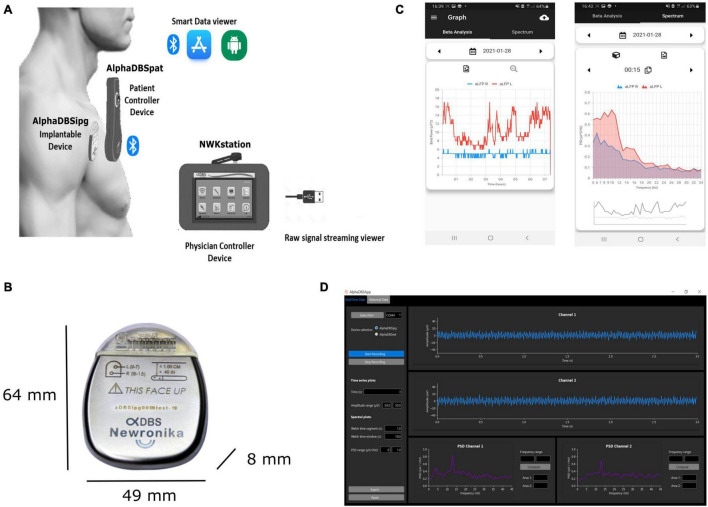
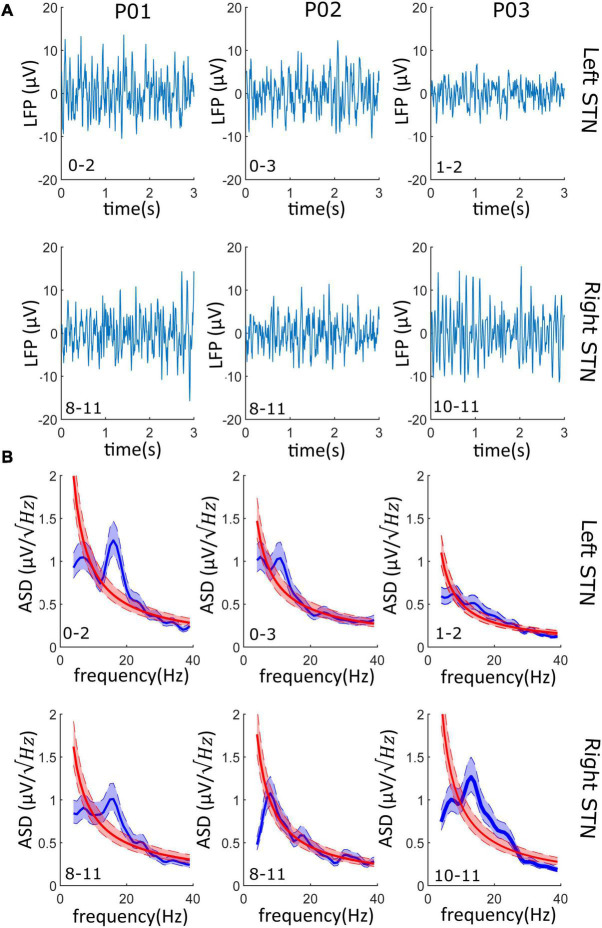
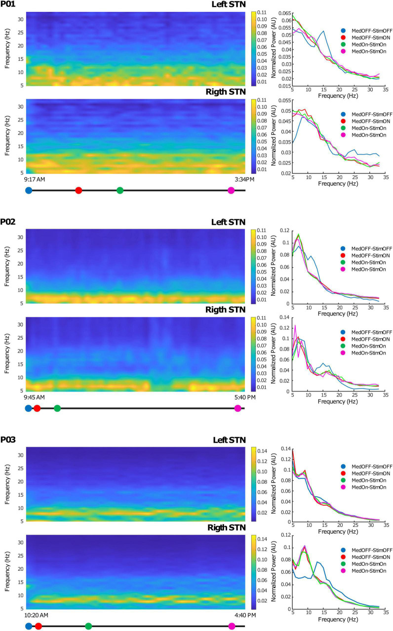
Deep brain stimulation (DBS) is used for the treatment of movement disorders, including Parkinson's disease, dystonia, and essential tremor, and has shown clinical benefits in other brain disorders. A natural path for the improvement of this technique is to continuously observe the stimulation effects on patient symptoms and neurophysiological markers. This requires the evolution of conventional deep brain stimulators to bidirectional interfaces, able to record, process, store, and wirelessly communicate neural signals in a robust and reliable fashion. Here, we present the architecture, design, and first use of an implantable stimulation and sensing interface (AlphaDBSR System) characterized by artifact-free recording and distributed data management protocols. Its application in three patients with Parkinson's disease (clinical trial n. NCT04681534) is shown as a proof of functioning of a clinically viable implanted brain-computer interface (BCI) for adaptive DBS. Reliable artifact free-recordings, and chronic long-term data and neural signal management are in place.

Keywords: Parkinson’s disease; closed-loop; deep brain stimulation; implantable device; local field potential (LFP); neural interface; neuromodulation.


Conflict of interest statement

MA and MC were employed by Newronika and held stock options. AB is a consultant for Newronika. AP, SM, and PR are founders and shareholders of Newronika. The study was funded by Newronika SpA. The funder had the following involvement with the study: study design of NCT04681534, signal collection and analysis (clinical data collection is performed by a CRO), the writing of this article, and the decision to submit it for publication. The remaining authors declare that the research was conducted in the absence of any commercial or financial relationships that could be construed as a potential conflict of interest.
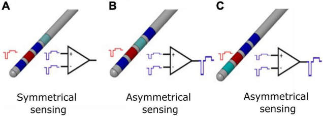
Figures

FIGURE 1
FIGURE 1
Differential sensing configurations for conventional DBS electrode. (A) Symmetrical sensing employs two recording contacts (blue) adjacent to the stimulation contact (red); at the inputs of the differential amplifier, the common mode stimulation artifact (in the ideal case of balanced impedances) is the same, and for an ideal common mode rejection ratio (CMMR), the output of the stimulation artifact is canceled by subtraction. (B) Asymmetrical sensing employs two recording contacts (blue) in the opposite position but at different distance compared to the stimulation contact (red), or two recording contacts (blue) in the same position and at different distance compared to the stimulation contact (red). At the inputs of the differential amplifier, the common mode stimulation artifacts (in the ideal case of balanced impedances) are not the same; even for an ideal CMMR, the output of the stimulation artifact is not canceled by subtraction. In real case scenario, impedances are unbalanced and the CMMR is not ideal; therefore, asymmetrical sensing implies a further worsening of the recording configuration. (C) Asymmetrical sensing with two adjacent contacts. The panel is organized as in (B) and the same comments apply.
FIGURE 2
FIGURE 2
AlphaDBS System architecture. (A) AlphaDBS System components: the AlphaDBSipg implantable device is recharged using a patient controller (AlphaDBSpat) that also allows downloading data and signals recorded using the embedded mode. A mobile app allows data visualization. The physician controller device (NWKstation) is used to program the AlphaDBSipg and to visualize LFPs recorded in the streaming mode. (B) AlphaDBSipg dimensions. (C) Screenshot of the mobile app showing beta band amplitude time changes (on the left) and power spectrum at a given time point (on the right). (D) Python-based GUI for real-time LFPs processing, visualization, and storing.
FIGURE 3
FIGURE 3
LFPs from the streaming mode: (A) Left and right LFPs time series. 3–s LFPs recordings are shown for both the left and right STN of each patient; on the bottom left corner, the contact pair used for recording is reported (i.e., “0–2” and “8–11”). (B) The PSD of the LFPs recordings of panel (a) is shown (blue line) and superimposed to the PSD of the 1/f background noise (red line). 95% confidence interval is shadowed around the PSD average (lighter blue and lighter red overlapped band). In at least one side per patient (four of the six recordings), the beta oscillations have a significative higher power than the background neural noise.
FIGURE 4
FIGURE 4
Chronic LFP recordings in the embedded mode: Left side: Time-frequency plots of six representative hours. The x-axis represents time and the y-axis frequency (from 5 to 35 Hz). The colored dots (blue, red, green, and magenta) correspond to clinical evaluations at MedOFF/StimOFF, MedOFF/StimON, MedON/StimON, and MedON/StimON, respectively. Right side: Amplitude spectrum of the LFPs of both the left and right STN extracted as the mean of the ± 10-min interval around the evaluation point (MedOFF/StimOFF, MedOFF/StimON, MedON/StimON, and MedON/StimON) obtained at the time indicated in the left side panels. Please note that, in MedOFF-StimOFF, a clear beta peak is present in the left STN of patients 01 and 02 and the right STN of patient 03. This beta peak was disappeared by the stimulation.

References

    1. Arlotti M., Marceglia S., Foffani G., Volkmann J., Lozano A. M., Moro E., et al. (2018). Eight-hours adaptive deep brain stimulation in patients with Parkinson disease. Neurology 90 e971–e976. 10.1212/WNL.0000000000005121 - DOI - PMC - PubMed
    1. Arlotti M., Palmisano C., Minafra B., Todisco M., Pacchetti C., Canessa A., et al. (2019). Monitoring subthalamic oscillations for 24 hours in a freely moving Parkinson’s disease patient. Mov. Disord. 34 757–759. 10.1002/mds.27657 - DOI - PMC - PubMed
    1. Arlotti M., Rosa M., Marceglia S., Barbieri S., Priori A. (2016a). The adaptive deep brain stimulation challenge. Parkinsonism Relat. Disord. 28 12–17. 10.1016/j.parkreldis.2016.03.020 - DOI - PubMed
    1. Arlotti M., Rossi L., Rosa M., Marceglia S., Priori A. (2016b). An external portable device for adaptive deep brain stimulation (aDBS) clinical research in advanced Parkinson’s Disease. Med. Eng. Phys. 38 498–505. 10.1016/j.medengphy.2016.02.007 - DOI - PubMed
    1. Beudel M., Brown P. (2016). Adaptive deep brain stimulation in Parkinson’s disease. Parkinsonism Relat. Disord. 22 S123–S126. 10.1016/j.parkreldis.2015.09.028 - DOI - PMC - PubMed

LinkOut - more resources