. 2021 Dec 18;21(24):8464.
doi: 10.3390/s21248464.

Batteryless, Miniaturized Implantable Glucose Sensor Using a Fluorescent Hydrogel

Affiliations

Batteryless, Miniaturized Implantable Glucose Sensor Using a Fluorescent Hydrogel

Hyeonkeon Lee et al. Sensors (Basel). .

Abstract

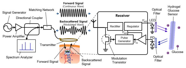
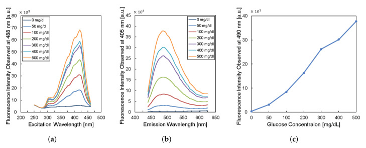
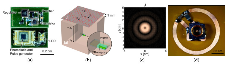
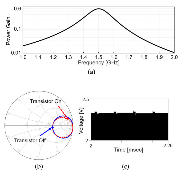
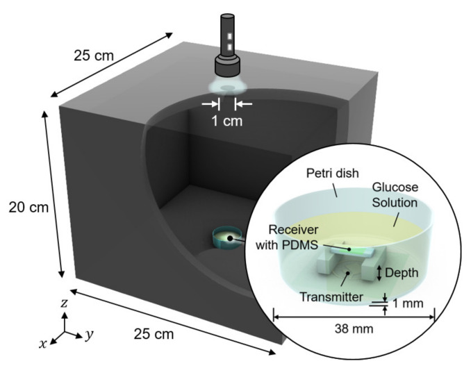
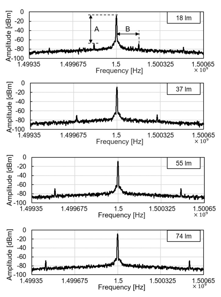
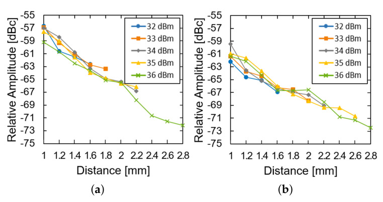
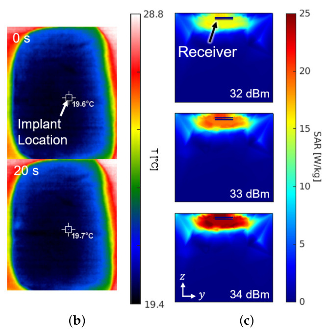
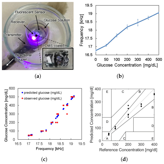
We propose a biomedical sensor system for continuous monitoring of glucose concentration. Despite recent advances in implantable biomedical devices, mm sized devices have yet to be developed due to the power limitation of the device in a tissue. We here present a mm sized wireless system with backscattered frequency-modulation communication that enables a low-power operation to read the glucose level from a fluorescent hydrogel sensor. The configuration of the reader structure is optimized for an efficient wireless power transfer and data communication, miniaturizing the entire implantable device to 3 × 6 mm 2 size. The operation distance between the reader and the implantable device reaches 2 mm with a transmission power of 33 dBm. We demonstrate that the frequency of backscattered signals changes according to the light intensity of the fluorescent glucose sensor. We envision that the present wireless interface can be applied to other fluorescence-based biosensors to make them highly comfortable, biocompatible, and stable within a body.

Keywords: WPT; batteryless; fluorescent; glucose; implantable; wireless.


Conflict of interest statement

The authors declare no conflict of interest.

Figures

Figure 1
Figure 1
Schematic illustration of the implantable continuous glucose monitoring system, including implantable hydrogel sensor, implantable frequency modulation module, and wearable transmitter.
Figure 2
Figure 2
Characteristics of fluorescent monomer response to the glucose levels. (a) The excitation profile and (b) the emission profile of the fluorescence sensor. (c) The fluorescence intensity observed at the wavelength of 490 nm versus glucose concentration.
Figure 3
Figure 3
(a) The fabricated sensor with the coil and the circuit components. It contains a loop antenna, matching network, rectifier, storage capacitor, and power transistor for shifting impedance (top) and photodiode and LED (bottom). (b) The planar model consists of a source surface current density J and a receiver coil placed within a tissue. The surface current source and the air–tissue interfaces are at the plane of z=0 and z=z1, respectively. The receiver is embedded at the depth of (z=zf). (c) The optimal current distribution at 1.5 GHz. (d) A coil structure for the transmitter that realizes the optimal current distribution.
Figure 4
Figure 4
Wireless link analysis in simulation. (a) Power gain plot is obtained by simulation that includes a s2p file modeling the coupling between Tx and Rx coil and matching networks. (b) Smith chart for S11 at the transmitter with the frequency range from 1 to 2 GHz. (c) Backscattered signal in time domain.
Figure 5
Figure 5
Measurement setup for wireless link analysis. The measurement was conducted in a dark chamber to avoid the interference from ambient light.
Figure 6
Figure 6
Backscattered signal measured by a spectrum analyzer with varying light intensity.
Figure 7
Figure 7
Measured results of the subtraction of the modulated signal from the carrier signal (a) in the air and (b) in the glucose solution according to the distance and transfer power.
Figure 8
Figure 8
(a) Photograph of the safety test setup within a piece of pork. (b) Top view of the pork with an infrared thermal image before (top) and after (bottom) powering for a duration of 20 s. (c) Cross section of the SAR simulation according to the input power.
Figure 8
Figure 8
(a) Photograph of the safety test setup within a piece of pork. (b) Top view of the pork with an infrared thermal image before (top) and after (bottom) powering for a duration of 20 s. (c) Cross section of the SAR simulation according to the input power.
Figure 9
Figure 9
(a) Photograph of in vitro glucose-response test setup. (b) Measured results of backscattered frequency versus glucose concentration. (c) Expectation of glucose level response by backscattered frequency. (d) Clarke’s error grid analysis of the whole system test.

References

    1. Zimmet P., Alberti K., Shaw J. Global and societal implications of the diabetes epidemic. Nature. 2001;414:782–787. doi: 10.1038/414782a. - DOI - PubMed
    1. Liao Y.T., Yao H., Lingley A., Parviz B., Otis B.P. A 3-uW CMOS Glucose Sensor for Wireless Contact-Lens Tear Glucose Monitoring. IEEE J.-Solid-State Circuits. 2011;47:335–344. doi: 10.1109/JSSC.2011.2170633. - DOI
    1. Mok J.W., Mun B.H., Lee K.J., Kamrani E., Joo C.K., Shin S., Sim J.Y., Myung D., Yun S.H., Bao Z., et al. Wireless smart contact lens for diabetic diagnosis and therapy. Sci. Adv. 2020;6:eaba3252. - PMC - PubMed
    1. Koh A., Kang D., Xue Y., Lee S., Pielak R.M., Kim J., Hwang T., Min S., Banks A., Bastien P., et al. A soft, wearable microfluidic device for the capture, storage, and colorimetric sensing of sweat. Sci. Transl. Med. 2016;8:366ra165. doi: 10.1126/scitranslmed.aaf2593. - DOI - PMC - PubMed
    1. Haider M.R., Islam S.K., Mostafa S., Zhang M., Oh T. Low-power low-voltage current readout circuit for inductively powered implant system. IEEE Trans. Biomed. Circuits Syst. 2010;4:205–213. doi: 10.1109/TBCAS.2010.2042809. - DOI - PubMed

LinkOut - more resources