. 2021;73(12):4248-4257.
doi: 10.1007/s11837-021-04963-w. Epub 2021 Nov 1.

A Perspective to Control Laser-Induced Periodic Surface Structure Formation at Glancing-Incident Femtosecond Laser-Processed Surfaces

Affiliations

A Perspective to Control Laser-Induced Periodic Surface Structure Formation at Glancing-Incident Femtosecond Laser-Processed Surfaces

Alexander Jelinek et al. JOM (1989). 2021.

Abstract

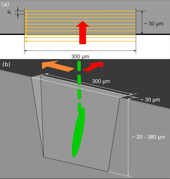
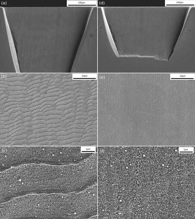
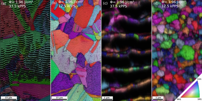
The favorable combination of high material removal rate and low influence on the material beneath the ultra-short pulsed laser-processed surface are of particular advantage for sample preparation. This is especially true at the micrometer scale or for the pre-preparation for a subsequent focused ion beam milling process. Specific surface features, the laser-induced periodic surface structures, are generated on femtosecond laser-irradiated surfaces in most cases, which pose an issue for surface-sensitive mechanical testing or microstructural investigations. This work strives for an approach to enhance the surface quality of glancing-incident laser-processed surfaces on the model material copper with two distinctly different grain sizes. A new generalized perspective is presented, in which optimized parameter selection serves to counteract the formation of the laser-induced periodic surface structures, enabling, for example, grain orientation mapping directly on femtosecond laser processed surfaces.

Supplementary information: The online version contains supplementary material available at 10.1007/s11837-021-04963-w.


Conflict of interest statement

Conflict of interestThe authors declare that they have no conflict of interest.

Figures

Fig. 1
Fig. 1
(a) Top view, in the laser beam propagation direction, of the processing pattern to obtain trenches for subsequent surface quality analysis. The field in gray represents the bulk material, where the thick black line depicts the sample edge. Unidirectional laser spot translation is indicated (thin orange arrows), which are stepwise parallel-shifted towards the sample center (thick red arrow) by al. (b) Idealized trench obtained by the processing pattern indicated in (a). Laser pulses (dashed green line) reaching the material surface causing stepwise ablation of the material, leaving a strongly inclined surface, where the projected pulse area (green oval) increases (Color figure online).
Fig. 2
Fig. 2
(a–c) Laser-processed trench in CG copper with increasing SEM magnification (Φ = 1.96 J/cm2, div = 50, s = 1 mm/s, l = 3, scans = 100 and al = 5 µm). LIPSS, well distinguished in (b) and detailed in (c), fully cover the trench indicated in (a). (d–f) Trench without LIPSS at identical SEM magnification steps as in (a–c) (Φ = 1.96 J/cm2, div = 50, s = 1 mm/s, l = 1, scans = 50 and al = 5 µm). In (c) a highly magnified image of the LIPSS is shown, which are covered with ablated surface, while in (f) only this last type of micro-roughness in the 10-nm regime is present.
Fig. 3
Fig. 3
Pulses per spot (PPS) versus fluence of each trench investigated. The points are marked with respect to the qualitative appearance of LIPSS. If even a small area of LIPSS formed, the parameter combination is marked with a black dot, otherwise, the parameter combination is denoted by a cross.
Fig. 4
Fig. 4
Evolution of average surface roughness with PPS for different fluence levels. The increase of roughness, with an onset at just below 18 k PPS, respectively 25 k, correlates with increasing areas covered with LIPSS. Once the whole region of interest is covered with LIPSS, the roughness saturates.
Fig. 5
Fig. 5
EBSD images (inverse pole figure with superimposed image quality) of CG copper (a, b) and UFG copper (c, d), whereby (a, c) are with and (b, d) without LIPSS according to the utilized parameter combination. On LIPSS-covered surfaces partly shadowing by the structures is evident, and an exact orientation mapping is hampered or even impossible. In the case of (a), single grains can be identified by crystallographic orientation, but a reliable mapping is not possible; even more so in (c), where the grain size is noticeably smaller than the LIPSS periodicity. On LIPSS-free surfaces in (b, d), EBSD scans can be reliably applied directly after laser processing. In the CG situation (b), a full scan is achieved, while in (d), even grains which are well below 500 nm in size can be identified.

References

    1. Chichkov BN, Momma C, Nolte S, von Alvensleben F, Tünnermann A. Appl. Phys. A. 1996;63:109. doi: 10.1007/BF01567637. - DOI
    1. Echlin MP, Straw M, Randolph S, Filevich J, Pollock TM. Mater. Charact. 2015;100:1. doi: 10.1016/j.matchar.2014.10.023. - DOI
    1. Wagner U, Petsch T, Krause M, Höche T. Proc. SPIE. 2016;9736:97360C. doi: 10.1117/12.2212444. - DOI
    1. Pfeifenberger MJ, Mangang M, Wurster S, Reiser J, Hohenwarter A, Pfleging W, Kiener D, Pippan R. Mater. Des. 2017;121:109. doi: 10.1016/j.matdes.2017.02.012. - DOI
    1. B. Tordoff, C. Hartfield, A.J. Holwell, S. Hiller, M. Kaestner, S. Kelly, J. Lee, S. Müller, F. Perez-Willard, T. Volkenandt, R. White and T. Rodgers, Appl. Microsc. 50, (2020). - PMC - PubMed

LinkOut - more resources