. 2022 Feb;32(2):176-189.
doi: 10.1038/s41422-021-00598-3. Epub 2022 Jan 3.

Structural insights into the membrane microdomain organization by SPFH family proteins

Affiliations

Structural insights into the membrane microdomain organization by SPFH family proteins

Chengying Ma et al. Cell Res. 2022 Feb.

Abstract

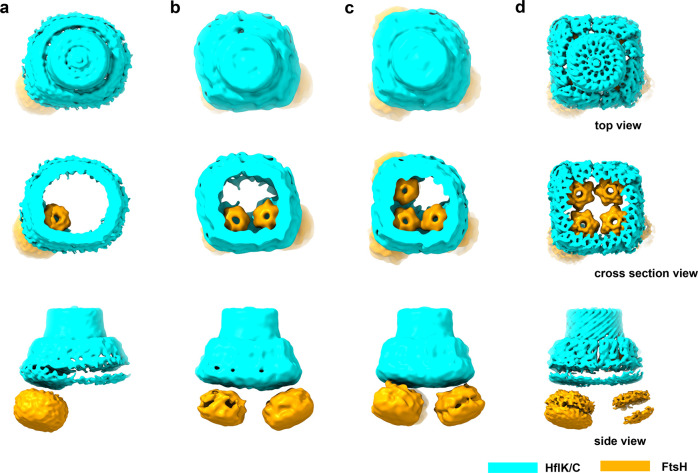
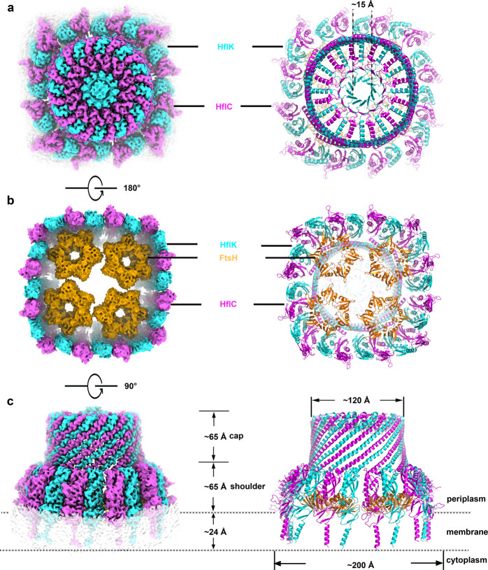
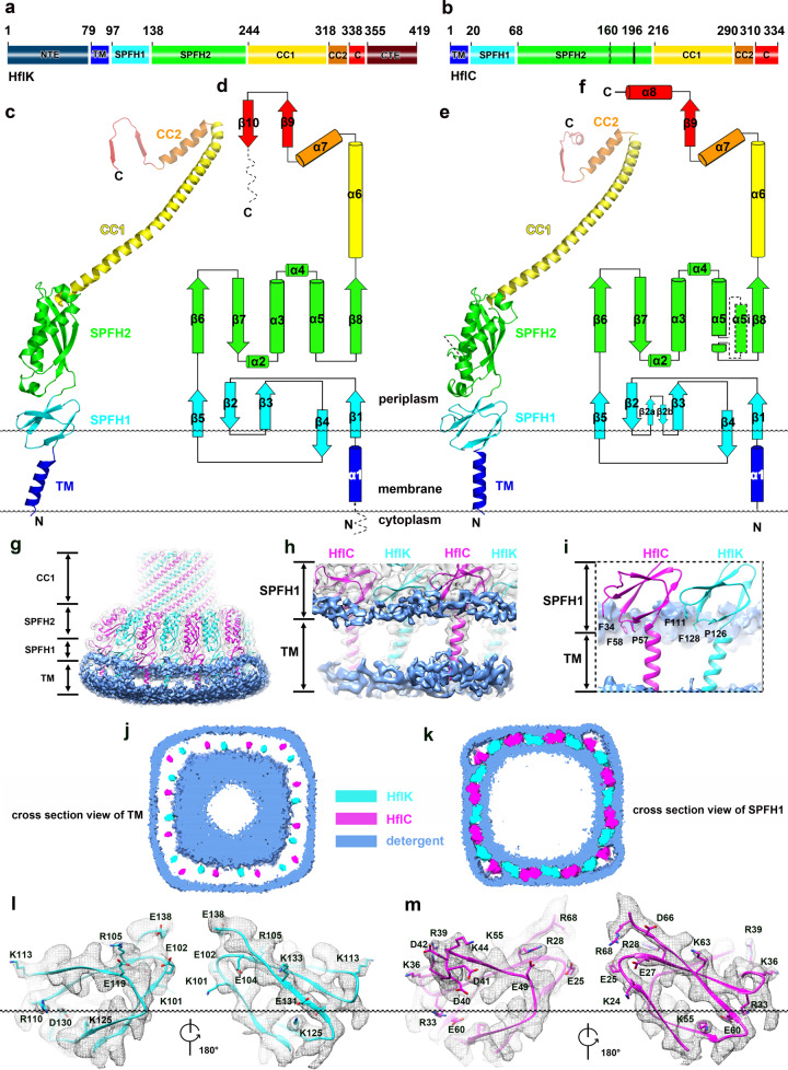
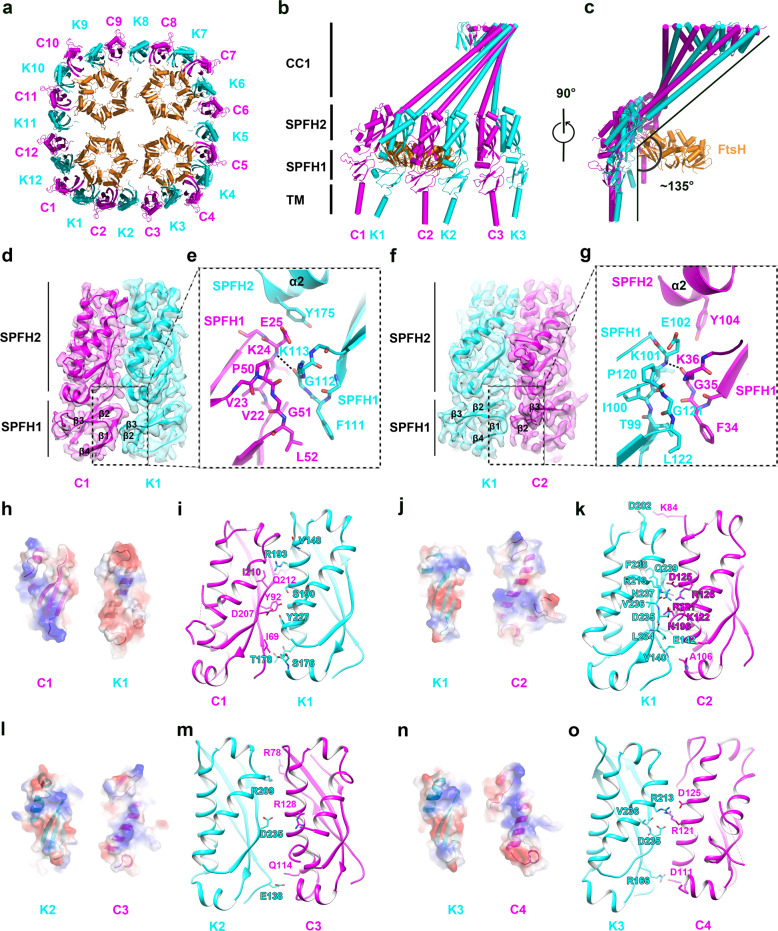
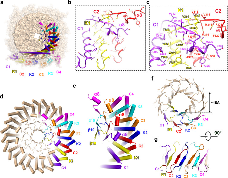
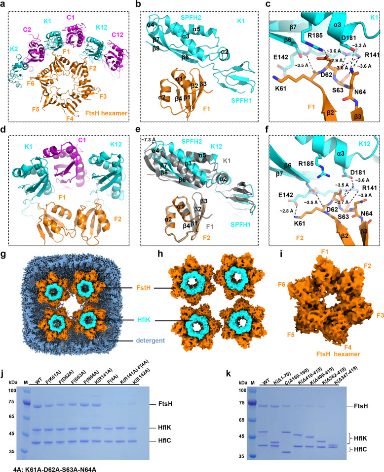
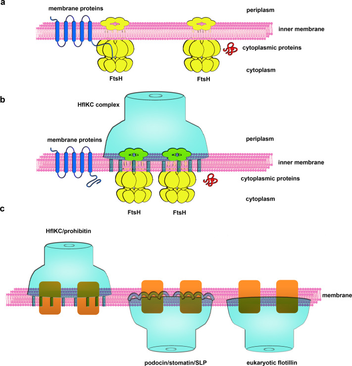
The lateral segregation of membrane constituents into functional microdomains, conceptually known as lipid raft, is a universal organization principle for cellular membranes in both prokaryotes and eukaryotes. The widespread Stomatin, Prohibitin, Flotillin, and HflK/C (SPFH) family proteins are enriched in functional membrane microdomains at various subcellular locations, and therefore were hypothesized to play a scaffolding role in microdomain formation. In addition, many SPFH proteins are also implicated in highly specific processes occurring on the membrane. However, none of these functions is understood at the molecular level. Here we report the structure of a supramolecular complex that is isolated from bacterial membrane microdomains and contains two SPFH proteins (HflK and HflC) and a membrane-anchored AAA+ protease FtsH. HflK and HflC form a circular 24-mer assembly, featuring a laterally segregated membrane microdomain (20 nm in diameter) bordered by transmembrane domains of HflK/C and a completely sealed periplasmic vault. Four FtsH hexamers are embedded inside this microdomain through interactions with the inner surface of the vault. These observations provide a mechanistic explanation for the role of HflK/C and their mitochondrial homologs prohibitins in regulating membrane-bound AAA+ proteases, and suggest a general model for the organization and functionalization of membrane microdomains by SPFH proteins.


Conflict of interest statement

The authors declare no competing interests.

Figures

Fig. 1
Fig. 1. Purified KCF complexes are heterogenous in conformation and composition.
ad The cryo-EM maps of intact KCF complexes with varying numbers of FtsH hexamers, showed in the top, vertical cross-section, and side views.
Fig. 2
Fig. 2. The overall structure of the intact KCF complex.
a Top view (periplasmic view) of the cryo-EM map (left) and atomic model (right) of the KCF complex. b Bottom view (cytoplasmic view) of the cryo-EM map (left) and atomic model (right) of the KCF complex. c Side view of the cryo-EM map (left) and atomic model (right) of the KCF complex. Subunits of HflK, HflC and FtsH are colored cyan, magenta and orange, respectively.
Fig. 3
Fig. 3. Structure and domain organization of HflK and HflC.
a, b Schematic illustration of the conserved domain organization of HflK and HflC, with individual domains separately colored. TM, blue; SPFH1, cyan; SPFH2, green; CC1, yellow; CC2, orange; CTD, red. The N-terminal and C-terminal extensions of HflK are denoted by NTE and CTE, respectively. c, d The atomic model (c) and the secondary structure topology of HflK (d). Secondary structural motifs are colored as in a. e, f The atomic model (e) and the secondary structure topology of HflC (f). Secondary structural motifs are colored as in b. g SPFH1 domains of HflK and HflC are peripheral membrane domains inserted in the outer leaflet of the membrane. The low-pass filtered cryo-EM map of the KCF complex is displayed in transparent surface representation, with atomic models of HflK (cyan) and HflC (magenta) superimposed. Detergent density is colored dodger blue. h Zoomed-in view of the TM regions of the KCF complex. i Same as h, with the removal of detergent density in the foreground. Two aromatic residues (F34 and F58 for HflC; F111 and F128 for HflK) located in the β2–β3 and β4–β5 loops are inserted in the membrane. j, k Vertical cross-section view of the density map of the KCF complex, in the position of the TM (j) and SPFH1 (k) regions. l, m The distribution of charged residues in the SPFH1 domains of HflK (l) and HflC (m). Note that membrane-buried polar residues often appear in pairs of opposite charge. R33 of HflC and R110 of HflK are highly conserved among SPFH family proteins from both prokaryotes and eukaryotes (see also Supplementary information, Fig. S6a).
Fig. 4
Fig. 4. Interface between HflK and HflC.
a A cutaway view of the KCF complex (viewed from the periplasmic side). HflK, HflC and FtsH are colored cyan, magenta and orange, respectively. Protomers of HflK (K1 to K12) and HflC (C1 to C12) are numbered anti-clockwisely. b, c Side view of a quarter of the KCF complex (one unsymmetrical unit). Subunits of HflK, HflC and FtsH are similarly colored as in a. d Domain interface between C1 and K1 in the SPFH1 region. The cryo-EM maps of the SPFH1 and SPFH2 domains are shown in transparent surface representation with atomic models superimposed. In the C1–K1 interface, the F111–G112–K113 loop (β2–β3 loop) of HflK contacts two loops (β1–β2 and β3–β4 loops) of HflC–SPHF1. e Detailed interactions between adjacent SPFH1 domains in the C1–K2 interface, including a hydrogen bond between main-chain atoms of G112 of K1 and K24 of C1, and a hydrophobic stacking between L52 of C1 and F111 of K1. f Same as d, but for the K1–C2 interface. In the C1–K2 interface, the F34–G35–K36 loop (β2–β3 loop) of HflC contacts two loops (β1–β2 and β3–β4 loops) of HflK-SPHF1. g Detailed interactions between adjacent SPFH1 domains in the C1–K2 interface, including a hydrogen bond between main-chain atoms of G35 of C2 and K101 of K1, and a hydrophobic stacking between L122 of K1 and F34 of C2. Note that the three interacting loops share identical sequences between HflK and HflC (See also Supplementary information, Fig. S6a). h Electrostatic surface potential of the interface between the SPFH2 domains of HflC (C1) and HflK (K1). i The C1–K1 interface is shown in cartoon representation, with interacting residues highlighted in stick models. jo Same as h and i, for the K1–C2 (j, k), K2–C3 (l, m) and K3–C4 (n, o) interfaces.
Fig. 5
Fig. 5. Structure and organization of the cap region of the KCF complex.
a Top view of the KCF complex, with seven subunits highlighted in ribbon representation and separately colored (C1, K1, C2, K2, C3, K3 and C4). b, c Zoomed-in view of boxed region in a. Extensive hydrophobic interactions contribute to the formation of the cap region (b). Detailed hydrophobic interactions between the α8-helix of HflC and juxtaposed CC2 subdomains of HflK and HflC (c). d Top view of the KCF complex, highlighting the overall organization of the cap region. e Enlarged view highlighting the positions of the C-termini of HflK and HflC. f, g Top (f) and side (g) views of the two-layered β-barrel in the cap region of the KCF complex. The outer layer is formed by 24 parallel β9-strands from HflK and HflC, and the inner layer by 12 parallel β10-strands of HflK.
Fig. 6
Fig. 6. Interactions between HflK and FtsH.
a Interaction between an FtsH hexamer and the inner wall of the HflK/C cage within a quarter of the KCF complex. Three FtsH periplasmic domains (F1, F2 and F6) are similarly orientated towards three copies of HflK (K1, K12 and K2), and two of them establish specific interactions. b, c Zoomed-in view showing the interactions between F1 and K1. The β2–β3 loop of FtsH contacts the linker sequence between the SPFH1 and SPFH2 domains of HflK (b). Detailed atomic interactions are highlighted in stick representation with distances labeled (c). d Same as a, with a further zoom in the two interacting FtsH periplasmic domains. e Structural comparison of the two FtsH–HflK interfaces (F1–K1 and F2–K12). Structural superimposition of F1–K1 and F2–K12 is derived using FtsH periplasmic domains as reference for alignment. F1 and K1 are colored gray. F2 and K12 were colored orange and cyan, respectively. f Same as c, but for the interface between F2 and K12. g Top view of the cryo-EM map of the KCF complex, highlighting the unmodelled density (cyan) above the hexameric periplasmic domain of FtsH. h Same as g, with detergent density removed. i Segmented cryo-EM map of a hexameric periplasmic domain of FtsH. j Point mutations on FtsH or HflK impair the binding of FtsH to the HflK/C cage. For each pull-down experiment with mutant variants, the C-terminally tagged HflC was used as bait and the loading was normalized using concentrations of HflC. k Truncations of HflK C-terminal sequences decrease the association of FtsH. For each pull-down experiment with mutant variants, the C-terminally tagged HflC was used as bait and the loading was normalized using concentrations of HflC.
Fig. 7
Fig. 7. The model of the KCF complex in membrane protein quality control and the structural basis of FMM organization by SPFH family proteins.
a FtsH hexamers degrade misfolded/damaged membrane proteins or cytoplasmic proteins. b HflK and HflC form a 24-mer circular assembly on the membrane, leading to the formation of 20-nm-sized microdomains bordered by the N-terminal TM domains of HflK/C. Up to four FtsH hexamers could be sequestered in these laterally segregated microdomains. HflK and HflC function as a negative modulator of FtsH to limit its substrate accessibility. c A general model for the FMM formation by SPFH family proteins. HflK/C, erlins and prohibitins contain a N-terminal TM segment, whereas stomatin, podocin and eukaryotic flotilins attach to the inner leaflet of the membrane through a hairpin helix or solely through lipidation of selected N-terminal residues. In all these cases, oligomerization of SPFH domains result in the formation of nanoscale microdomains on specific leaflets of the membranes.

Comment in

References

    1. Simons K, Ikonen E. Functional rafts in cell membranes. Nature. 1997;387:569–572. - PubMed
    1. Lingwood D, Simons K. Lipid rafts as a membrane-organizing principle. Science. 2010;327:46–50. - PubMed
    1. Sezgin E, Levental I, Mayor S, Eggeling C. The mystery of membrane organization: composition, regulation and roles of lipid rafts. Nat. Rev. Mol. Cell Biol. 2017;18:361–374. - PMC - PubMed
    1. Lopez D, Kolter R. Functional microdomains in bacterial membranes. Genes Dev. 2010;24:1893–1902. - PMC - PubMed
    1. Lucena D, Mauri M, Schmidt F, Eckhardt B, Graumann PL. Microdomain formation is a general property of bacterial membrane proteins and induces heterogeneity of diffusion patterns. BMC Biol. 2018;16:97. - PMC - PubMed

Publication types

MeSH terms