

Super-resolution confocal cryo-CLEM with cryo-FIB milling for in situ imaging of Deinococcus radiodurans
- PMID: 34977598
- PMCID: PMC8688812
- DOI: 10.1016/j.crstbi.2021.12.001
Super-resolution confocal cryo-CLEM with cryo-FIB milling for in situ imaging of Deinococcus radiodurans
Abstract
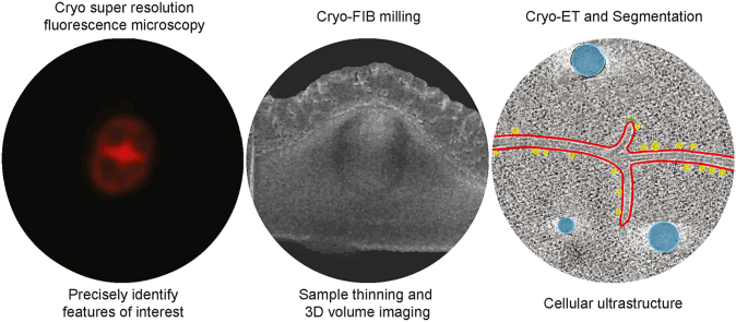
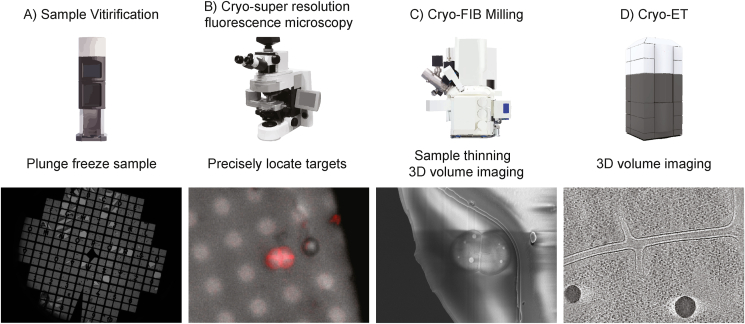
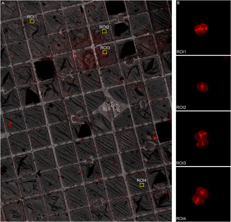
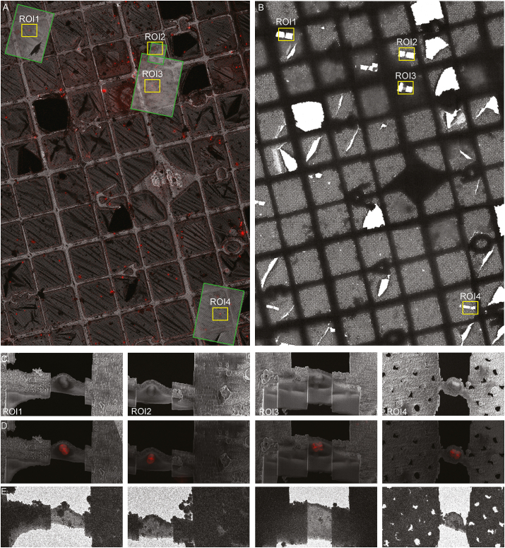
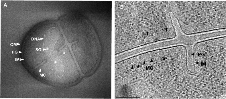
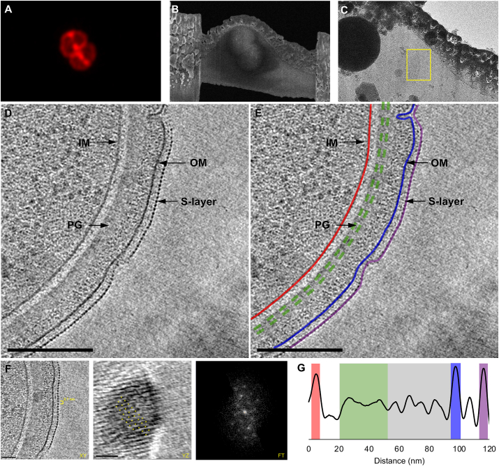
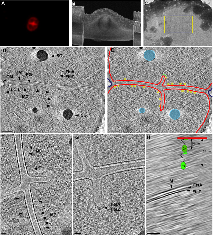
Studying bacterial cell envelope architecture with electron microscopy is challenging due to the poor preservation of microbial ultrastructure with traditional methods. Here, we established and validated a super-resolution cryo-correlative light and electron microscopy (cryo-CLEM) method, and combined it with cryo-focused ion beam (cryo-FIB) milling and scanning electron microscopy (SEM) volume imaging to structurally characterize the bacterium Deinococcus radiodurans. Subsequent cryo-electron tomography (cryo-ET) revealed an unusual diderm cell envelope architecture with a thick layer of peptidoglycan (PG) between the inner and outer membranes, an additional periplasmic layer, and a proteinaceous surface S-layer. Cells grew in tetrads, and division septa were formed by invagination of the inner membrane (IM), followed by a thick layer of PG. Cytoskeletal filaments, FtsA and FtsZ, were observed at the leading edges of constricting septa. Numerous macromolecular complexes were found associated with the cytoplasmic side of the IM. Altogether, our study revealed several unique ultrastructural features of D. radiodurans cells, opening new lines of investigation into the physiology and evolution of the bacterium.
Keywords: Cell envelope architecture; Cryo-CLEM; Cryo-ET; Cryo-FIB; Cryo-super resolution microscopy; Microbial ultrastructure.
© 2021 The Authors.
Conflict of interest statement
The authors declare that they have no known competing financial interests or personal relationships that could have appeared to influence the work reported in this paper.
Figures
Similar articles
-
Advanced cryo-tomography workflow developments - correlative microscopy, milling automation and cryo-lift-out.J Microsc. 2021 Feb;281(2):112-124. doi: 10.1111/jmi.12939. Epub 2020 Jul 2. J Microsc. 2021. PMID: 32557536
-
Cryo-correlative light and electron microscopy workflow for cryo-focused ion beam milled adherent cells.Methods Cell Biol. 2021;162:273-302. doi: 10.1016/bs.mcb.2020.12.009. Epub 2021 Feb 17. Methods Cell Biol. 2021. PMID: 33707016
-
Combining live fluorescence imaging with in situ cryoelectron tomography sheds light on the septation process in Deinococcus radiodurans.Proc Natl Acad Sci U S A. 2025 May 13;122(19):e2425047122. doi: 10.1073/pnas.2425047122. Epub 2025 May 6. Proc Natl Acad Sci U S A. 2025. PMID: 40327694
-
Cryo-focused-ion-beam applications in structural biology.Arch Biochem Biophys. 2015 Sep 1;581:122-30. doi: 10.1016/j.abb.2015.02.009. Epub 2015 Feb 20. Arch Biochem Biophys. 2015. PMID: 25703192 Review.
-
Advances in Cryo-Correlative Light and Electron Microscopy: Applications for Studying Molecular and Cellular Events.Protein J. 2019 Dec;38(6):609-615. doi: 10.1007/s10930-019-09856-1. Protein J. 2019. PMID: 31396855 Review.
Cited by
-
Insights into protein structure using cryogenic light microscopy.Biochem Soc Trans. 2023 Dec 20;51(6):2041-2059. doi: 10.1042/BST20221246. Biochem Soc Trans. 2023. PMID: 38015555 Free PMC article. Review.
-
Visualizing the virus world inside the cell by cryo-electron tomography.J Virol. 2024 Dec 17;98(12):e0108523. doi: 10.1128/jvi.01085-23. Epub 2024 Nov 4. J Virol. 2024. PMID: 39494908 Free PMC article. Review.
-
A new age in structural S-layer biology: Experimental and in silico milestones.J Biol Chem. 2025 Jun;301(6):110205. doi: 10.1016/j.jbc.2025.110205. Epub 2025 May 8. J Biol Chem. 2025. PMID: 40345586 Free PMC article. Review.
-
Cryo-electron tomography on focused ion beam lamellae transforms structural cell biology.Nat Methods. 2023 Apr;20(4):499-511. doi: 10.1038/s41592-023-01783-5. Epub 2023 Mar 13. Nat Methods. 2023. PMID: 36914814 Review.
-
Recent advances and current trends in cryo-electron microscopy.Curr Opin Struct Biol. 2022 Dec;77:102484. doi: 10.1016/j.sbi.2022.102484. Epub 2022 Oct 28. Curr Opin Struct Biol. 2022. PMID: 36323134 Free PMC article. Review.
References
-
- Baumeister W., Karrenberg F., Rachel R., Engel A., ten Heggeler B., Saxton W.O. The major cell envelope protein of Micrococcus radiodurans (R1). Structural and chemical characterization. Eur. J. Biochem. 1982;125:535–544. - PubMed
-
- Betzig E., Patterson G.H., Sougrat R., Lindwasser O.W., Olenych S., Bonifacino J.S., et al. Imaging intracellular fluorescent proteins at nanometer resolution. Science. 2006;313:1642–1645. - PubMed
-
- Bruch E.M., de Groot A., Un S., Tabares L.C. The effect of gamma-ray irradiation on the Mn(II) speciation in Deinococcus radiodurans and the potential role of Mn(II)-orthophosphates. Metall. 2015;7:908–916. - PubMed
LinkOut - more resources
Full Text Sources
