. 2022 Feb;16(1):64-78.
doi: 10.1109/TBCAS.2022.3140591. Epub 2022 May 9.

Design and Optimization of Ultrasonic Links With Phased Arrays for Wireless Power Transmission to Biomedical Implants

Design and Optimization of Ultrasonic Links With Phased Arrays for Wireless Power Transmission to Biomedical Implants

Zeinab Kashani et al. IEEE Trans Biomed Circuits Syst. 2022 Feb.

Abstract

Ultrasound (US) is an attractive modality for wireless power transfer (WPT) to biomedical implants with millimeter (mm) dimensions. To compensate for misalignments in WPT to a mm-sized implant (or powering a network of mm-sized implants), a US transducer array should electronically be driven in a beamforming fashion (known as US phased array) to steer focused US beams at different locations. This paper presents the theory and design methodology of US WPT links with phased arrays and mm-sized receivers (Rx). For given constraints imposed by the application and fabrication, such as load (RL) and focal distance (F), the optimal geometries of a US phased array and Rx transducer, as well as the optimal operation frequency (fc) are found through an iterative design procedure to maximize the power transfer efficiency (PTE). An optimal figure of merit (FoM) related to PTE is proposed to simplify the US array design. A design example of a US link is presented and optimized for WPT to a mm-sized Rx with a linear array. In measurements, the fabricated 16-element array (10.9×9×1.7 mm3) driven by 100 V pulses at fc of 1.1 MHz with optimal delays for focusing at F = 20 mm generated a US beam with a pressure output of 0.8 MPa. The link could deliver up to 6 mW to a ∼ 1 mm3 Rx with a PTE of 0.14% (RL = 850 Ω). The beam steering capability of the array at -45o to 45o angles was also characterized.


Figures

Fig. 1.
Fig. 1.
Conceptual schematic of a US WPT link for powering mm-sized implants uisng a US phased array as the power transmitter (Tx).
Fig. 2.
Fig. 2.
A linear US phased array with a conceptual beam shape, consisting of near- and far-field zones.
Fig. 3.
Fig. 3.
k-Wave simulation setup used to optimize an array for US WPT. The array surface is parallel to the yz plane and centered at the origin x = y = z = 0. Both the xy and xz planes were defined as sensors for recording US pressure.
Fig. 4.
Fig. 4.
Iterative optimization flowchart of a US link with a phased array for efficient WPT to mm-sized biomedical implants. The proposed procedure needs to be completed in COMSOL and k-Wave.
Fig. 5.
Fig. 5.
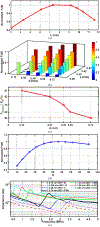
Geometry optimization of the US array at fc =1.4 MHz, F = 30 mm, and Pθs,max/P00.7 at θs,max = 45°, showing (a) normalized FoM vs. L, (b) normalized FoM vs. d and a, (c) Pθs,max/P0 at θs,max = 45° vs. d, (d) normalized FoM vs. N, and (e) array element impedance vs. frequency to find optimal t.
Fig. 6.
Fig. 6.
Simulated beam profiles of the optimal array in the xy and yz planes when the beam was focused at F = 30 mm and θs = 0° (fc = 1.4 MHz).
Fig. 7.
Fig. 7.
(a) Fabrication procedure of the linear US array using a dicing machine. (b) Fabricated mm-sized US receiver (Rx).
Fig. 8.
Fig. 8.
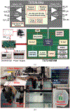
(a) Block diagram of the TX7316EVM evaluation board for driving the US array in our measurements. (b) Ultrasonic WPT link measurement setup inside a water tank without and with a chicken breast mimicking tissue.
Fig. 9.
Fig. 9.
Measured impedance profile of (a) all 16 elements of the fabricated linear US array at a frequency range of 0.6–1.5 MHz, and (b) Rx transducer at a frequency range of 0.8–2 MHz.
Fig. 10.
Fig. 10.
(a) Measured US pressure output at 20 mm axial distance (20 V peak-peak sinusoids) of individual elements in the fabricated 16-element array, and (b) measured electrical input power of each element at the same conditions.
Fig. 11.
Fig. 11.
Optimal delay patterns of each element of US array obtained from k-Wave simulations for beamforming (a) at different focal depths F with θs = 0°, and (b) at different steering angles θs with F = 20 mm.
Fig. 12.
Fig. 12.
Measured transient waveforms of the driver board across 4 US elements (# 2, 5, 12, 15 in Fig. 7) for beamforming at F = 20 mm with (a) θs = 0° and (b) θs = 45°. (c) Burst-mode signal generated by the driver and the received voltage by the Rx transducer (F = 20 mm, θs = 0°).
Fig. 13.
Fig. 13.
Simulated and measured beam profiles of the 16-element array in the xy plane at F = 20 mm with different θs of a) 0°, b) 45°, and c) −45°
Fig. 14.
Fig. 14.
Simulated and measured beam profiles of the 16-element array in the xy plane at F = 20 mm (θs = 0°) in the presence of the chicken breast.
Fig. 15.
Fig. 15.
Measured received power PL (θs = 0°) by the Rx transducer vs. RL at a depth of F = 20 mm while driving the array at different voltages.
Fig. 16.
Fig. 16.
Measured highest PTE of the US WPT link for different RL, when the beam was focused at F = 20 mm (θs = 0°).
Fig. 17.
Fig. 17.
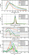
Measured PL with beam focusing and steering at different F and θs (RL = 850 Ω). (a) PL at different axial distances at different F. (b) PL at different lateral distances at different F. (c) PL at different axial distances at different θs, and (d) PL at different lateral distances at different θs.
Fig. 18.
Fig. 18.
Measured PL along the axial axis x at zero and 13.2 mm lateral (y) distances when the beam was focused at F = 20 mm and θs = 0° and 45°.

References

    1. Chen K, Yang Z, Hoang L, Weiland J, Humayun M, and Liu W, “An integrated 256-channel epiretinal prosthesis,” IEEE J. Solid State Cir, vol. 45, pp. 1946–1956, Sep. 2010.
    1. McConnell G, Rees H, Levey A, Gutekunst C, Gross R, and Bellamkonda R, “Implanted neural electrodes cause chronic, local inflammation that is correlated with local neurodegeneration,” J. Neural Eng, vol. 6, p. 056003, Oct. 2009. - PubMed
    1. Sekhon B, “Bioelectronic medicine/electroceuticals – The emergence of new electronic therapeutics,” Int. J. Nov. Res. Eng. Pharm. Sci, vol 1, pp. 58–63, Mar. 2014.
    1. Kiani M, Jow UM, and Ghovanloo M, “Design and optimization of a 3-coil inductive link for efficient wireless power transmission,” IEEE Trans. Biomed. Cir. Syst, vol. 5, no. 6, pp. 579–591, Dec. 2011. - PMC - PubMed
    1. Jow U and Ghovanloo M, “Design and optimization of printed spiral coils for efficient transcutaneous inductive power transmission,” IEEE Trans. Biomed. Cir. Syst, vol. 1, pp. 193–202, Sept. 2007. - PubMed

Publication types