Review
. 2021 Dec;8(4):041326.
doi: 10.1063/5.0070658.

Understanding and utilizing textile-based electrostatic flocking for biomedical applications

Affiliations
Review

Understanding and utilizing textile-based electrostatic flocking for biomedical applications

Alec McCarthy et al. Appl Phys Rev. 2021 Dec.

Abstract

Electrostatic flocking immobilizes electrical charges to the surface of microfibers from a high voltage-connected electrode and utilizes Coulombic forces to propel microfibers toward an adhesive-coated substrate, leaving a forest of aligned fibers. This traditional textile engineering technique has been used to modify surfaces or to create standalone anisotropic structures. Notably, a small body of evidence validating the use of electrostatic flocking for biomedical applications has emerged over the past several years. Noting the growing interest in utilizing electrostatic flocking in biomedical research, we aim to provide an overview of electrostatic flocking, including the principle, setups, and general and biomedical considerations, and propose a variety of biomedical applications. We begin with an introduction to the development and general applications of electrostatic flocking. Additionally, we introduce and review some of the flocking physics and mathematical considerations. We then discuss how to select, synthesize, and tune the main components (flocking fibers, adhesives, substrates) of electrostatic flocking for biomedical applications. After reviewing the considerations necessary for applying flocking toward biomedical research, we introduce a variety of proposed use cases including bone and skin tissue engineering, wound healing and wound management, and specimen swabbing. Finally, we presented the industrial comments followed by conclusions and future directions. We hope this review article inspires a broad audience of biomedical, material, and physics researchers to apply electrostatic flocking technology to solve a variety of biomedical and materials science problems.


Figures

FIG. 1.
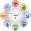
FIG. 1.
Industries and applications utilizing electrostatic flocking.
FIG. 2.
FIG. 2.
Schematic illustration of electrostatic flocking set-ups with a (a) bottom-to-top configuration using a charging electrode and (b) a top-to-bottom configuration using a charged sieve box. Schematics inspired by excerpts and reproduced with permissions from Kim, Specialist yarn and fabric structures, in Specialist yarn and fabric structures, edited by R. H. Gong (pp. 287–317). Copyright 2011 Elsevier.
FIG. 3.
FIG. 3.
Charging methods used to impart surface charges onto flock fibers. (a) Contact charging on a plate electrode showing movement of charges (left) and accumulation of charges (right), (b) corona discharge, and (c) tribocharging, where fibers make contact with and slide along a surface (left) to accumulate mix of positive and negative charges (right). Schematics inspired by excerpts and reproduced with permission from Kim, Specialist yarn and fabric structures, in Specialist yarn and fabric structures, edited by R. H. Gong (pp. 287–317). Copyright 2011 Elsevier.
FIG. 4.
FIG. 4.
Characterization of porosity and fiber density of flocked scaffolds. (a–d) SEM images of flocked scaffolds using 1 mm and 3 mm fibers for 5 s and 15 s illustrating differences in fiber density. (e) Delaunay–Voronoi triangulation used to calculate the Euclidian distance between adjacent chitosan fibers. Reproduced with permission from Walther et al., Materials. 5, 540 (2012). Copyright 2021 MDPI. (f) Frequency distribution plot of the Euclidian distance between adjacent chitosan fibers. Reproduced with permission from Gosssla et al., Acta Biomater. 44, 267 (2016). Copyright 2016 Elsevier.
FIG. 5.
FIG. 5.
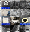
Methods used to create microfibers suitable for electrostatic flocking and their accompanying SEM micrographs. Schematics inspired and adapted from Ali et al., Electrospinning of continuous nanofiber bundles and twisted nanofiber yarns, in Nanofibers – Production, Properties and Functional Applications, edited by T. Lin (pp. 154–166). Copyright 2011 IntechOpen. (a) Wet spinning. Reproduced with permission from McCarthy et al., Adv. Healthc. Mater. 10, 2100766 (2021). Copyright 2021 Wiley. (b) Wet electrospinning. Reproduced with permission from Smit et al., Polymer 8, 2419 (2005). Copyright 2005 Elsevier. (c) Yarn electrospinning. Reproduced with permission from Wu et al., Acta Biomater. 62, 102 (2017). Copyright 2017 Elsevier. (d) Melt spinning. Reproduced with permission Zhao et al., Adv. Funct. Mater. 28 (2018). Copyright 2018, Wiley.
FIG. 6.
FIG. 6.
Machines and representative schematics for preparing flock fibers from continuous fiber tow: (a) (i) Pierret P26 vertical precision short cut fiber cutting machine and (ii) cutting mechanism employed by vertical cutting. Photograph supplied and reproduced with permission from Pierret International. (b) A Van der Mast Fiber Chopper Chopcot® T6 rotary short fiber cutter and (ii) rotary cutting mechanism of action. Photograph supplied and reproduced with permission from Van der Mast. (c) An example of precision short-cut fluorescent flock fibers and (d) longer standard flock fibers prepared by Spectro Coating Corp. Photographs supplied and printed with permission from Spectro Coating Corp. (e) A novel, lab-appropriate technique to prepare thermoplastic flock fibers that uses (i) aligned fiber freezing, (ii) cryocutting, (iii) and water separation. Reproduced with permission from M. Cole, Sci. Rep. 6, 34519 (2016). Copyright 2016 Nature Publishing Group.
FIG. 7.
FIG. 7.
Mechanisms of flocking. (a) Surface resistance as a function of relative humidity (RH) using different fiber finishes. Reproduced with permission from Ramadan and Ingamells, J. Soc. Dye. Colour 108, 270 (1992). Copyright 1992 Wiley. (b) The flock activity of finished fibers at different RH. (c–d) Rayon and AgNP/PCL fibers flocked at different RH showing different responses to the same RH conditions. Reproduced with permission from McCarthy et al., Adv. Healthc. Mater. 10, 2100766 (2021). Copyright 2021 Wiley.
FIG. 8.
FIG. 8.
Potential flocking substrates with preselected biomedical applications. (a) 3D printed multi-layered mesh, (b) electrospun nanofiber mat, and (c) self-folding hierarchical conduits. Reproduced with permission from McCarthy et al., Adv. Healthc. Mater. 10, 2100766 (2021). Copyright 2021 Wiley.
FIG. 9.
FIG. 9.
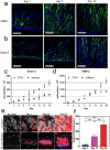
Cellular response to flocked scaffolds. (a) hMSCs cultured on pure chitosan scaffodls for 14 days. (b) Saos-2 cells cultured on pure chitosan scaffolds over 14 days. Scale bar = 400 um. (c) Saos-2 and (d) hMSC proliferation cell counts after 14 days of culture. Reproduced with permission from Gosssla et al., Acta Biomater. 44, 267 (2016). Copyright 2016 Elsevier Ltd. (e) Actin/DAPI stained hMSCs cultured on AgNP/PCL flocked scaffolds for 28 days. (f) Distance of leading cell edge migrated over a 28-day culture period. Reproduced with permission from McCarthy et al., Adv. Healthc. Mater. 10, 2100766 (2021). Copyright 2021 Wiley.
FIG. 10.
FIG. 10.
Improving orthopedic outcomes with electrostatically flocked tissue scaffolds. Proposed uses of flocked tissue scaffolds for (a) repairing cranial defects and (b) osteochondral engineering of joints to treat arthritis and cartilage defects. (c) Illustration representing composite flock scaffolds with gradient mechanical properties matching different regions of cortical and trabecular bone.
FIG. 11.
FIG. 11.
Flocked AgNP/PCL fiber and chitosan adhesive/substrate scaffolds demonstrate a modest and significant cranial bone regeneration effect in a rat cranial model. (a) Micro computed tomography images of rat cranial bone defects untreated and treated with low and high-density flocked scaffolds for 7 weeks. (b) Scaffold orientation in situ (substrate flush with dura mater). (c) Graph comparing recovered bone volume (%) between each group (P < 0.05, n = 4). Reproduced from A. McCarthy, unpublished Ph.D. Dissertation (2021). Copyright 2021 University of Nebraska Medical Center.
FIG. 12.
FIG. 12.
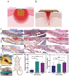
Proposed methods to incorporate flocked constructors for wound healing and skin tissue engineering. (a) Flock implants form granulation tissue or (b) are paired with absorptive materials to facilitate blood absorption and hemostasis in acute wounds. (c) Subcutaneous implantation of AgNP/PCL scaffolds shows a fiber-dependent granulation tissue formation. Scale bar = 1 mm and 200 um for 10× and 40× images. (d) Schematic outlining the surgical procedures for flock scaffold implantation. (e and f) The fiber-dependent angiogenetic and penetration response from flocked scaffolds implanted in a mouse model. Reproduced with permission from McCarthy et al., Adv. Healthc. Mater. 10, 2100766 (2021). Copyright 2021 Wiley.
FIG. 13.
FIG. 13.
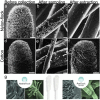
Flocked swabs for sample extraction. (a–c) SEM images of nylon flocked swabs before collection, after sampling (presence of bacteria), and after extraction (absence of bacteria). (d–f) SEM images of traditional cotton swabs before collection, after sampling (presence of bacteria), and after extraction (absence of bacteria). Scale bar in (a, d, f) = 1 mm. Scale bar in (b, c, e) = 5 um. Reproduced with permission from Probst et al., Appl. Environ. Microbiol. 76, 15 (2010). Copyright 2010 American Society for Microbiology. (g) Photograph and SEM images of two FDA approved flocked swabs developed by Puritan Medical Products, with the HydraFlock® on the left and the PurFlock® on the right. Photograph supplied and reproduced with permission from Puritan Medical Products.

References

    1. Kim Y. K., Specialist Yarn and Fabric Structures ( Elsevier, 2011), pp. 287–317.
    1. King W. H., U.S. Patent Office (29 May 1945).
    1. Vellayappan M. V., Jaganathan S. K., and Supriyanto E., RSC Adv. 5, 73225–73240 (2015).10.1039/C5RA11937E - DOI
    1. Gokarneshan N., Curr. Trends Fashion Technol. Text. Eng. 4, 555630 (2018).10.19080/CTFTTE.2018.04.555630 - DOI
    1. Uetani K., Ata S., Tomonoh S., Yamada T., Yumura M., and Hata K., Adv. Mater. 26, 5857–5862 (2014).10.1002/adma.201401736 - DOI - PubMed

LinkOut - more resources