

A Review: Laser Welding of Dissimilar Materials (Al/Fe, Al/Ti, Al/Cu)-Methods and Techniques, Microstructure and Properties
- PMID: 35009268
- PMCID: PMC8746029
- DOI: 10.3390/ma15010122
A Review: Laser Welding of Dissimilar Materials (Al/Fe, Al/Ti, Al/Cu)-Methods and Techniques, Microstructure and Properties
Abstract
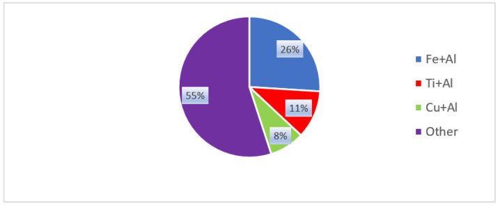
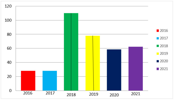
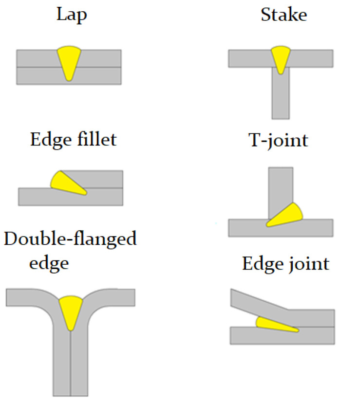
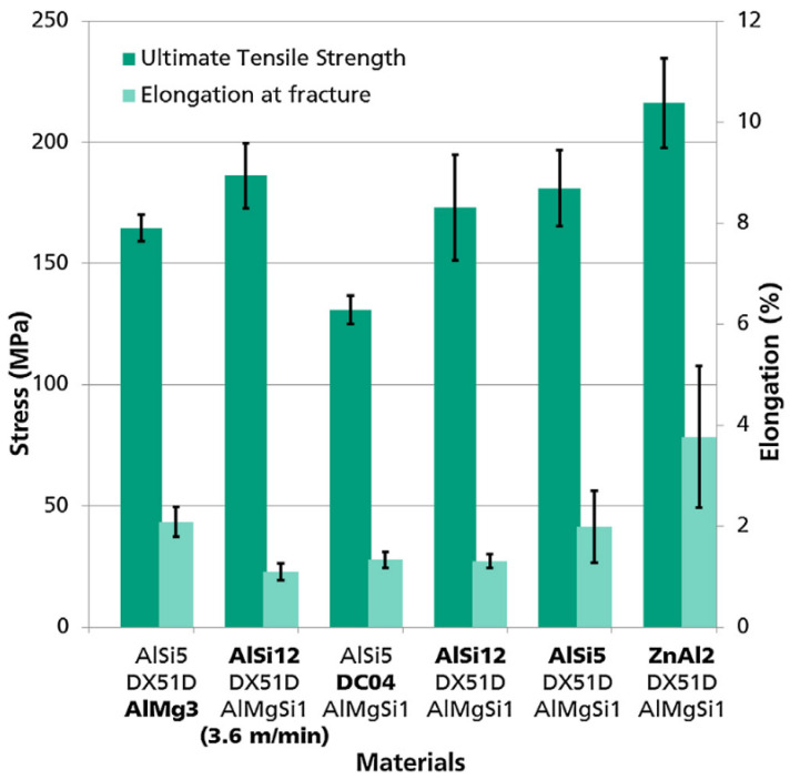
Modern structural engineering is impossible without the use of materials and structures with high strength and low specific weight. This work carries out a quantitative and qualitative analysis of articles for 2016-2021 on the topic of welding of dissimilar alloys. It is found that laser welding is most widely used for such metal pairs as Al/Fe, Al/Ti, and Al/Cu. The paper analyzes the influence of the basic techniques, methods, and means of laser welding of Al/Fe, Al/Ti, and Al/Cu on the mechanical properties and thickness of the intermetallic compound (IMC). When welding the lap joint or spike T-joint configuration of Al/Fe, it is preferable to melt the steel, which will be heated or melted, by the laser beam, and through thermal conduction, it will heat the aluminum. When welding the butt-welded joint of Al/Fe, the most preferable is to melt the aluminum by the laser beam (150-160 MPa). When welding the butt-welded joint of Al/Ti, it is possible to obtain the minimum IMC and maximum mechanical properties by offsetting the laser beam to aluminum. Whereas when the laser beam is offset to a titanium alloy, the mechanical properties are 40-50% lower than when the laser beam is offset to an aluminum alloy. When lap welding the Al/Cu joint, under the impact of the laser beam on the aluminum, using defocusing or wobbling (oscillation) of a laser beam, it is possible to increase the contact area of electrical conductivity with the tensile shear strength of 95-128 MPa.
Keywords: dissimilar metals; intermetallic layer; laser welding; mechanical properties; microstructure; weldability.
Conflict of interest statement
The author declares no conflict of interest.
Figures

Similar articles
-
Numerical Simulation of Temperature Fields during Laser Welding-Brazing of Al/Ti Plates.Materials (Basel). 2023 Mar 11;16(6):2258. doi: 10.3390/ma16062258. Materials (Basel). 2023. PMID: 36984138 Free PMC article.
-
Effect of Laser Beam Oscillation on Laser Welding-Brazing of Ti/Al Dissimilar Metals.Materials (Basel). 2019 Dec 11;12(24):4165. doi: 10.3390/ma12244165. Materials (Basel). 2019. PMID: 31835860 Free PMC article.
-
The Study on Mechanical Strength of Titanium-Aluminum Dissimilar Butt Joints by Laser Welding-Brazing Process.Materials (Basel). 2019 Feb 28;12(5):712. doi: 10.3390/ma12050712. Materials (Basel). 2019. PMID: 30823499 Free PMC article.
-
Progressive developments and challenges in dissimilar laser welding of steel to various other light alloys (Al/Ti/Mg): A comprehensive review.Heliyon. 2022 Nov 18;8(11):e11710. doi: 10.1016/j.heliyon.2022.e11710. eCollection 2022 Nov. Heliyon. 2022. PMID: 36468141 Free PMC article. Review.
-
A Review of Dissimilar Welding Techniques for Magnesium Alloys to Aluminum Alloys.Materials (Basel). 2014 May 8;7(5):3735-3757. doi: 10.3390/ma7053735. Materials (Basel). 2014. PMID: 28788646 Free PMC article. Review.
Cited by
-
Functionally Graded Materials and Structures: Unified Approach by Optimal Design, Metal Additive Manufacturing, and Image-Based Characterization.Materials (Basel). 2024 Sep 16;17(18):4545. doi: 10.3390/ma17184545. Materials (Basel). 2024. PMID: 39336286 Free PMC article.
-
Research on Filling Strategy of Pipeline Multi-Layer Welding for Compound Narrow Gap Groove.Materials (Basel). 2022 Aug 29;15(17):5967. doi: 10.3390/ma15175967. Materials (Basel). 2022. PMID: 36079353 Free PMC article.
-
Microstructure and Mechanical Properties of Laser-Welded Joints between DP590 Dual-Phase Steel and 304 Stainless Steel with Preset Nickel Coating.Materials (Basel). 2023 Mar 30;16(7):2774. doi: 10.3390/ma16072774. Materials (Basel). 2023. PMID: 37049067 Free PMC article.
-
Advances in Experimentation and Numerical Modeling of Aluminum and Copper Ultrasonic Welding.Micromachines (Basel). 2025 Feb 26;16(3):263. doi: 10.3390/mi16030263. Micromachines (Basel). 2025. PMID: 40141874 Free PMC article. Review.
-
Numerical Simulation of Temperature Fields during Laser Welding-Brazing of Al/Ti Plates.Materials (Basel). 2023 Mar 11;16(6):2258. doi: 10.3390/ma16062258. Materials (Basel). 2023. PMID: 36984138 Free PMC article.
References
-
- Martinsen K., Hu S.J., Carlson B.E. Joining of dissimilar materials. CIRP Ann. 2015;64:679–699. doi: 10.1016/j.cirp.2015.05.006. - DOI
-
- Seffer O., Pfeifer R., Springer A., Kaierle S. Investigations on laser beam welding of different dissimilar joints of steel and aluminum alloys for automotive lightweight construction. Phys. Procedia. 2016;83:383–395. doi: 10.1016/j.phpro.2016.08.040. - DOI
-
- Wiley C.P. In: Handbook of Lightweight Engineering Materials. 1st ed. Degischer H.P., editor. Wiley-VCH; Weinheim, Germany: 2017. p. 450.
-
- Sakundarini N., Taha Z., Abdul-Rashid S.H., Ghazila R.A.R. Optimal multi-material selection for lightweight design of automotive body assembly incorporating recyclability. Mater. Des. 2013;50:846–857. doi: 10.1016/j.matdes.2013.03.085. - DOI
-
- Schwartz M. Soldering–Understanding the Basics. ASM International; New York, NY, USA: 2014.
Publication types
LinkOut - more resources
Full Text Sources
Research Materials
