. 2021 Dec 24;22(1):97.
doi: 10.3390/s22010097.

Determination of the Geometric Parameters of Electrode Systems for Electrical Impedance Myography: A Preliminary Study

Affiliations

Determination of the Geometric Parameters of Electrode Systems for Electrical Impedance Myography: A Preliminary Study

Andrey Briko et al. Sensors (Basel). .

Abstract

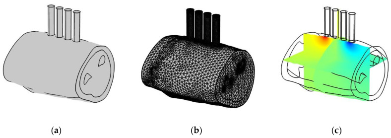
The electrical impedance myography method is widely used in solving bionic control problems and consists of assessing the change in the electrical impedance magnitude during muscle contraction in real time. However, the choice of electrode systems sizes is not always properly considered when using the electrical impedance myography method in the existing approaches, which is important in terms of electrical impedance signal expressiveness and reproducibility. The article is devoted to the determination of acceptable sizes for the electrode systems for electrical impedance myography using the Pareto optimality assessment method and the electrical impedance signals formation model of the forearm area, taking into account the change in the electrophysical and geometric parameters of the skin and fat layer and muscle groups when performing actions with a hand. Numerical finite element simulation using anthropometric models of the forearm obtained by volunteers' MRI 3D reconstructions was performed to determine a sufficient degree of the forearm anatomical features detailing in terms of the measured electrical impedance. For the mathematical description of electrical impedance relationships, a forearm two-layer model, represented by the skin-fat layer and muscles, was reasonably chosen, which adequately describes the change in electrical impedance when performing hand actions. Using this model, for the first time, an approach that can be used to determine the acceptable sizes of electrode systems for different parts of the body individually was proposed.

Keywords: MRI reconstruction; Pareto optimality; bionic control; electrical impedance; electrode system; mathematical model; neuromuscular interface; orthoses; physical modeling; prosthesis.


Conflict of interest statement

The authors declare no conflict of interest.

Figures

Figure A1
Figure A1
EI model (a) and the results of comparison EI simulated with the analytical one (b) to determine the geometric dimensions.
Figure A2
Figure A2
Various dividing models for the computational grid: (a) solid model; (b) global division; (c) local refinement; (d) uniformly increasing division.
Figure A3
Figure A3
Cylindrical models with different ratios of radius to interelectrode distance: (a) R/a = 1, (b) R/a = 3, (c) R/a = 10.
Figure A4
Figure A4
Simplification of the homogeneous cylindrical model to a planar one (R is the cylindrical model radius; a is the interelectrode distance).
Figure 1
Figure 1
An example of the ES size and location for upper limb EI myography.
Figure 2
Figure 2
EI myography conditioning mechanisms: (a) change in muscle resistivity; (b) changes in skin-fat layer thickness (h1 is the skin-fat layer thickness; h2 is the muscle tissues thickness; ρ1 is the skin-fat layer electrical resistivity, ρ2 is the muscle tissues electrical resistivity).
Figure 3
Figure 3
Potential distribution in the forearm anatomical model simulation by the finite element method: (a) geometric representation of the model; (b) discretization of the model into geometric primitives; (c) potential distribution.
Figure 4
Figure 4
Research algorithm in COMSOL Multiphysics 5.4.
Figure 5
Figure 5
Volunteers’ forearms MRI images reconstruction: (a) MRI slice; (b) contouring of the slice; (c) contoured slices series; (d) forearm 3D reconstruction.
Figure 6
Figure 6
Model simplification error investigation: (a) anatomical; (b) single cut; (c) ellipsoidal; (d) one-dimensional forearm MRI sections; (e) cylindrical (for 16 slices); (f) planar.
Figure 7
Figure 7
EI simulation results for anatomical and simplified models (Z is an absolute EI value).
Figure 8
Figure 8
(a) Longitudinal forearm ultrasound investigation; (b) a homogeneous half-space two-layer model, represented by the skin-fat layer and muscle tissues, A and B—CE, M and N—PE; ρ1 is the skin-fat layer electrical resistance, ρ2 is the muscle tissues electrical resistivity, h1 is the skin-fat layer thickness.
Figure 9
Figure 9
Relationship between the AR relative change and the ratio of the first layer thickness to the interelectrode distance (left) and its projection on the volunteer’s forearm MRI (girth 0.35 m) for ES with an interelectrode distance 0.01 m (right).
Figure 10
Figure 10
Relationship between the two-layer model EI expression partial derivatives and the interelectrode distance.
Figure 11
Figure 11
Relationship between the interelectrode distance values and the skin-fat layer thickness.
Figure 12
Figure 12
(a) Pareto frontier; (b) global multiobjective problem statement.
Figure 13
Figure 13
Pareto sets for EI sensitivity criteria.
Figure 14
Figure 14
The Pareto optimal solutions are set for the interelectrode distance choice.
Figure 15
Figure 15
Example of transverse ultrasound images of internal structures of the forearm: (a) at rest; (b) when performing a wrist extension; (c) with an increase in the pressing force of the ultrasonic sensor to the skin surface.
Figure 16
Figure 16
Multiobjective optimization problem solving for dZdh1/Z и dZdρ2/Z.

Similar articles

Cited by

References

    1. Kobelev A.V., Shchukin S.I. 2018 Ural Symposium on Biomedical Engineering, Radioelectronics and Information Technology (USBEREIT) IEEE; New York, NY, USA: 2018. Anthropomorphic prosthesis control based on the electrical impedance signals analysis; pp. 33–36. - DOI
    1. Lo H.S., Xie S.Q. Exoskeleton robots for upper-limb rehabilitation: State of the art and future prospects. Med. Eng. Phys. 2012;34:261–268. doi: 10.1016/j.medengphy.2011.10.004. - DOI - PubMed
    1. Cordella F., Ciancio A.L., Sacchetti R., Davalli A., Cutti A.G., Guglielmelli E., Zollo L. Literature review on needs of upper limb prosthesis users. Front. Neurosci. 2016;10:209. doi: 10.3389/fnins.2016.00209. - DOI - PMC - PubMed
    1. Osborn L.E., Iskarous M.M., Thakor N.V. Wearable Robotics. Elsevier; Amsterdam, The Netherlands: 2020. Sensing and control for prosthetic hands in clinical and research applications; pp. 445–468. - DOI
    1. Mooney L.M., Rouse E.J., Herr H.M. Autonomous exoskeleton reduces metabolic cost of human walking during load carriage. J. Neuroeng. Rehabil. 2014;11:80. doi: 10.1186/1743-0003-11-80. - DOI - PMC - PubMed

LinkOut - more resources