

Volumetric and multispectral DWI near metallic implants using a non-linear phase Carr-Purcell-Meiboom-Gill diffusion preparation
- PMID: 35014729
- PMCID: PMC8979554
- DOI: 10.1002/mrm.29153
Volumetric and multispectral DWI near metallic implants using a non-linear phase Carr-Purcell-Meiboom-Gill diffusion preparation
Abstract
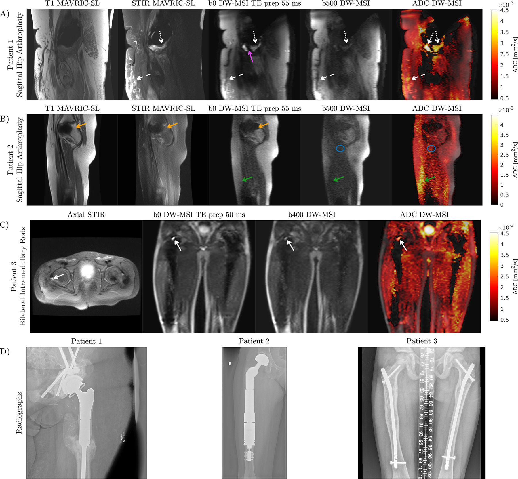
Purpose: DWI near metal implants has not been widely explored due to substantial challenges associated with through-slice and in-plane distortions, the increased encoding requirement of different spectral bins, and limited SNR. There is no widely adopted clinical protocol for DWI near metal since the commonly used EPI trajectory fails completely due to distortion from extreme off-resonance ranging from 2 to 20 kHz. We present a sequence that achieves DWI near metal with moderate b-values (400-500 s/mm2 ) and volumetric coverage in clinically feasible scan times.
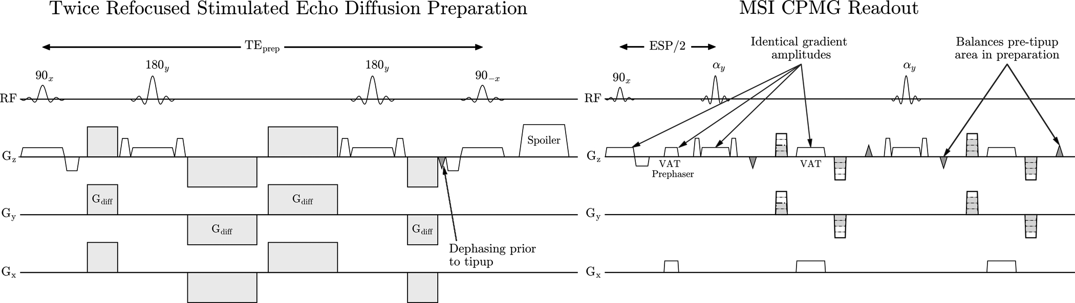
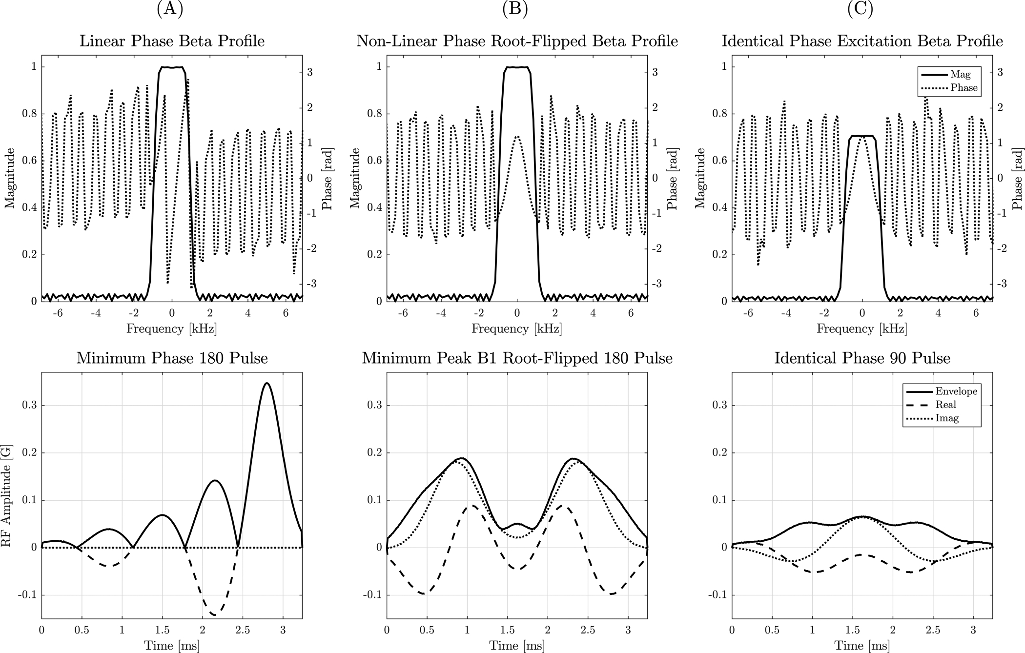
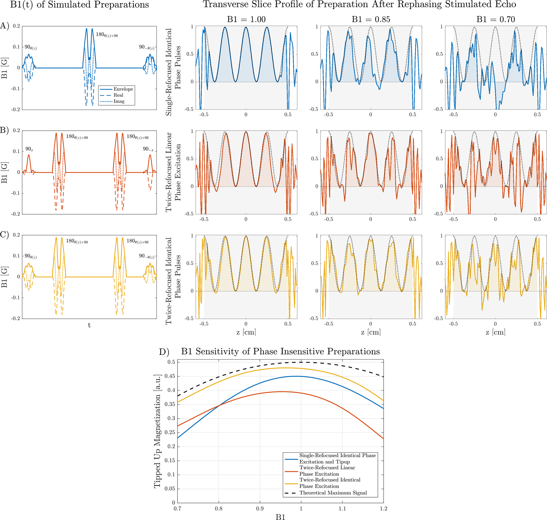
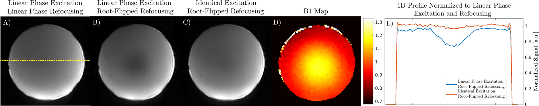
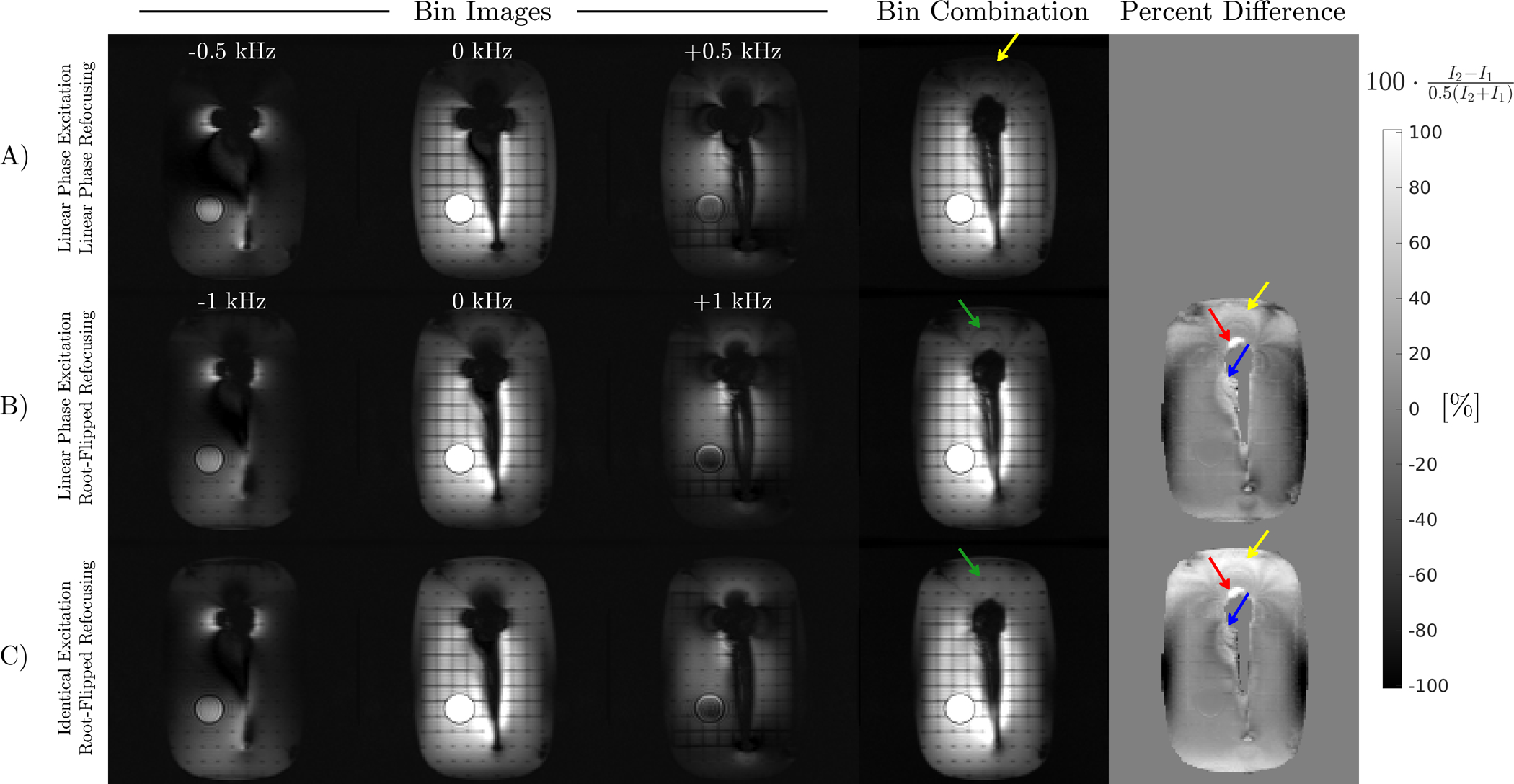
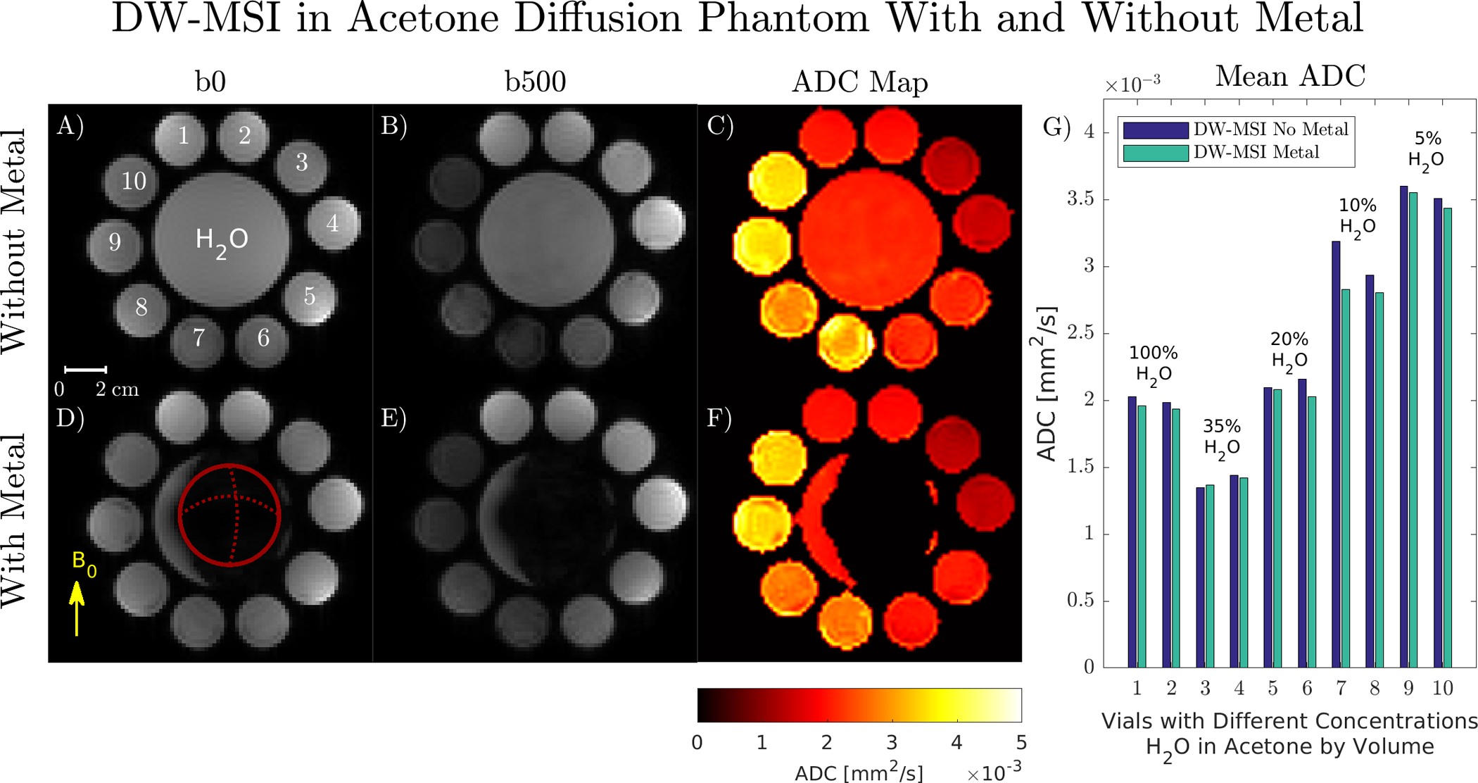
Theory and methods: Multispectral excitation with Cartesian sampling, view angle tilting, and kz phase encoding reduce in-plane and through-plane off-resonance artifacts, and Carr-Purcell-Meiboom-Gill (CPMG) spin-echo refocusing trains counteract T2* effects. The effect of random phase on the refocusing train is eliminated using a stimulated echo diffusion preparation. Root-flipped Shinnar-Le Roux refocusing pulses permits preparation of a high spectral bandwidth, which improves imaging times by reducing the number of excitations required to cover the desired spectral range. B1 sensitivity is reduced by using an excitation that satisfies the CPMG condition in the preparation. A method for ADC quantification insensitive to background gradients is presented.
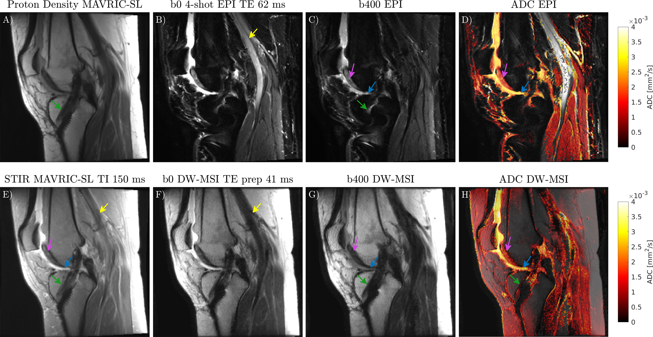
Results: Non-linear phase refocusing pulses reduces the peak B1 by 46% which allows RF bandwidth to be doubled. Simulations and phantom experiments show that a non-linear phase CPMG pulse pair reduces B1 sensitivity. Application in vivo demonstrates complementary contrast to conventional multispectral acquisitions and improved visualization compared to DW-EPI.
Conclusion: Volumetric and multispectral DW imaging near metal can be achieved with a 3D encoded sequence.
Keywords: diffusion preparation; diffusion weighted imaging; distortionless diffusion; multispectral imaging; root-flipped SLR pulses.
© 2022 International Society for Magnetic Resonance in Medicine.
Figures
Similar articles
-
Multiband Fast Spin Echo on portable low-field systems.Magn Reson Med. 2025 Aug 11. doi: 10.1002/mrm.70036. Online ahead of print. Magn Reson Med. 2025. PMID: 40785549
-
Single-shot multi-b-value (SSMb) diffusion-weighted MRI using spin echo and stimulated echoes with variable flip angles.NMR Biomed. 2024 Dec;37(12):e5261. doi: 10.1002/nbm.5261. Epub 2024 Sep 22. NMR Biomed. 2024. PMID: 39308034 Free PMC article.
-
Comparison of Diffusion-Weighted MRI Using Single-Shot Echo-Planar Imaging and Split Acquisition of Fast Spin-Echo Signal Imaging, a Non-EPI Technique, in Tumors of the Head and Neck.AJNR Am J Neuroradiol. 2025 Apr 2;46(4):774-783. doi: 10.3174/ajnr.A8529. AJNR Am J Neuroradiol. 2025. PMID: 39384329
-
The clinical significance of diffusion-weighted MR imaging in stroke and TIA patients.Swiss Med Wkly. 2008 Dec 13;138(49-50):729-40. doi: 10.4414/smw.2008.12249. Swiss Med Wkly. 2008. PMID: 19130326
-
[Volume and health outcomes: evidence from systematic reviews and from evaluation of Italian hospital data].Epidemiol Prev. 2013 Mar-Jun;37(2-3 Suppl 2):1-100. Epidemiol Prev. 2013. PMID: 23851286 Italian.
Cited by
-
Influence of angioplasty and stenting on intracranial artery stenosis: preliminary results of high-resolution vessel wall imaging evaluation.Eur Radiol. 2022 Oct;32(10):6788-6799. doi: 10.1007/s00330-022-09010-z. Epub 2022 Jul 19. Eur Radiol. 2022. PMID: 35852577
-
Diffusion Weighted Magnetic Resonance Imaging of Spinal Cord Injuries After Instrumented Fusion Stabilization.J Neurotrauma. 2024 Sep;41(17-18):2125-2132. doi: 10.1089/neu.2023.0591. Epub 2024 Apr 10. J Neurotrauma. 2024. PMID: 38251658
-
Diffusion-weighted MRI of the spinal cord in cervical spondylotic myelopathy after instrumented fusion.Front Neurol. 2023 May 19;14:1172833. doi: 10.3389/fneur.2023.1172833. eCollection 2023. Front Neurol. 2023. PMID: 37273696 Free PMC article.
References
-
- Martin BI, Mirza SK, Spina N, Spiker WR, Lawrence B, Brodke DS. Trends in Lumbar Fusion Procedure Rates and Associated Hospital Costs for Degenerative Spinal Diseases in the United States, 2004 to 2015. Spine 2019;44(5):369–376. - PubMed
-
- Koch KM, Brau AC, Chen W, Gold GE, Hargreaves BA, Koff M, et al. Imaging Near Metal with a MAVRIC-SEMAC Hybrid. Magnetic Resonance in Medicine 2011. jan;65(1):71–82. http://doi.wiley.com/10.1002/mrm.22523. - DOI - PubMed
-
- Lu W, Pauly KB, Gold GE, Pauly JM, Hargreaves BA. SEMAC: Slice encoding for metal artifact correction in MRI. Magnetic Resonance in Medicine 2009. jul;62(1):66–76. http://doi.wiley.com/10.1002/mrm.21967. - DOI - PMC - PubMed
Publication types
MeSH terms
Grants and funding
LinkOut - more resources
Full Text Sources
