Review
. 2022 Mar;9(7):e2105084.
doi: 10.1002/advs.202105084. Epub 2022 Jan 17.

A New Class of Electronic Devices Based on Flexible Porous Substrates

Affiliations
Review

A New Class of Electronic Devices Based on Flexible Porous Substrates

Yiyuan Zhang et al. Adv Sci (Weinh). 2022 Mar.

Abstract

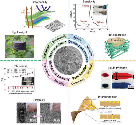
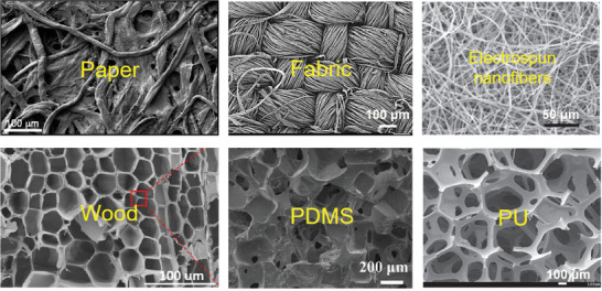
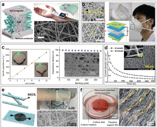
With the advent of the Internet of Things era, the connection between electronic devices and humans is getting closer and closer. New-concept electronic devices including e-skins, nanogenerators, brain-machine interfaces, and implantable medical devices, can work on or inside human bodies, calling for wearing comfort, super flexibility, biodegradability, and stability under complex deformations. However, conventional electronics based on metal and plastic substrates cannot effectively meet these new application requirements. Therefore, a series of advanced electronic devices based on flexible porous substrates (e.g., paper, fabric, electrospun nanofibers, wood, and elastic polymer sponge) is being developed to address these challenges by virtue of their superior biocompatibility, breathability, deformability, and robustness. The porous structure of these substrates can not only improve device performance but also enable new functions, but due to their wide variety, choosing the right porous substrate is crucial for preparing high-performance electronics for specific applications. Herein, the properties of different flexible porous substrates are summarized and their basic principles of design, manufacture, and use are highlighted. Subsequently, various functionalization methods of these porous substrates are briefly introduced and compared. Then, the latest advances in flexible porous substrate-based electronics are demonstrated. Finally, the remaining challenges and future directions are discussed.

Keywords: biocompatibility; breathability; deformability; electronic device; flexible porous substrate; pore structure.


Conflict of interest statement

The authors declare no conflict of interest.

Figures

Figure 1
Figure 1
The advantages of flexible porous substrates for electronic products in terms of user experience, device performance, mechanical property, and pore function. “Light weight”: Reproduced with permission.[ 13 ] Copyright 2017, The Royal Society of Chemistry. “Breathability”: Reproduced with permission.[ 14 ] Copyright 2017, Wiley‐VCH. “Sensitivity”: Reproduced with permission.[ 15 ] Copyright 2018, Wiley‐VCH. “Ink absorption”: Reproduced with permission.[ 16 ] Copyright 2018, Wiley‐VCH. “Robustness”: Reproduced with permission.[ 19 ] Copyright 2017, Wiley‐VCH. “Flexibility”: Reproduced with permission.[ 20 ] Copyright 2017, Springer Nature. “Interconnection”: Reproduced with permission.[ 18 ] Copyright 2018, Wiley‐VCH. “Liquid transport”: Reproduced with permission.[ 21 ] Copyright 2019, Wiley‐VCH.
Figure 2
Figure 2
The micromorphology of the typical flexible porous substrates. “Paper”: Reproduced with permission.[ 29 ] Copyright 2018, Wiley‐VCH. “Fabric”: Reproduced with permission.[ 30 ] Copyright 2018, Elsevier. “Electrospun nanofibers”: Reproduced with permission.[ 31 ] Copyright 2014, Wiley‐VCH. “Wood”: Reproduced with permission.[ 32 ] Copyright 2020, American Chemical Society. “PDMS”: Reproduced with permission.[ 33 ] Copyright 2021, Springer Nature. “PU”: Reproduced with permission.[ 34 ] Copyright 2016, Wiley‐VCH.
Figure 3
Figure 3
Important criteria for the selection of paper substrates. “Paper”: Reproduced with permission.[ 58 ] Copyright 2019, The Royal Society of Chemistry. “Ink permeability”: Reproduced with permission.[ 59 ] Copyright 2019, American Chemical Society. “Bendability”: Reproduced with permission.[ 35 ] Copyright 2018, Wiley‐VCH. “Transparency”: Reproduced with permission.[ 60 ] Copyright 2009, Wiley‐VCH. “Printing resolution”: Reproduced with permission.[ 61 ] Copyright 2019, American Chemical Society. “Paper electrodes in various solvents”: Reproduced with permission.[ 62 ] Copyright 2016, The Royal Society of Chemistry. “Low‐cost Al‐air batteries”: Reproduced with permission.[ 63 ] Copyright 2019, Elsevier.
Figure 4
Figure 4
Examples of using the porous structure of papers to realize new functions and improve device performance. a) Controlling the printing resolution by adjusting the paper's capillarity. Reproduced with permission.[ 62 ] Copyright 2016, The Royal Society of Chemistry. b) Optical and SEM images of the paper‐based capacitor fabricated by copper ELD. Reproduced with permission.[ 35 ] Copyright 2018, Wiley‐VCH. c) Integrating electronics and microfluidics on paper. Reproduced with permission.[ 36 ] Copyright 2016, Wiley‐VCH. d) Hygroexpansive electrothermal paper actuator activated by the change of moisture content. Reproduced with permission.[ 37 ] Copyright 2016, Wiley‐VCH. e) Monolithic flexible SCs integrated into single sheets of paper. Reproduced with permission.[ 67 ] Copyright 2017, Wiley‐VCH. f) Porous paper enables a thick deposition layer of TE particles without blocking the pores. Reproduced with permission.[ 59 ] Copyright 2019, American Chemical Society. g) TENG based on heterostructured air‐laid paper. Reproduced with permission.[ 38 ] Copyright 2019, Wiley‐VCH. h) Hierarchically nanostructured cellulose fiber‐based TENG. Reproduced with permission.[ 75 ] Copyright 2018, Wiley‐VCH.
Figure 5
Figure 5
Examples of using the porous structure of fabrics to improve device performance include stretchability, triboelectric output performance, conductivity, sensitivity, and heat dissipation rate. a) The stretchable fabric offers strain limiting support to keep the device's integrity until 220% strain. Reproduced with permission.[ 39 ] Copyright 2014, Springer Nature. b) A whole‐textile TENG by weaving Ni‐coated polyester fabric electrodes with high power density. Reproduced with permission.[ 40 ] Copyright 2015, Wiley‐VCH. c) A highly conductive interdigital electrode fabricated on a cotton fabric via Ni ELD. Reproduced with permission.[ 83 ] Copyright 2019, Wiley‐VCH. d) Ionic liquid activated wearable sensors based on cotton fabric with enhanced sensitivity. Reproduced with permission.[ 41 ] Copyright 2019, Elsevier. e) Highly porous heating fabrics with exceptional heat dissipation properties. Reproduced with permission.[ 87 ] Copyright 2018, Elsevier.
Figure 6
Figure 6
Examples of using electrospun nanofibers to realize various high‐performance flexible electronics. a) Two‐layered e‐textile patches. Reproduced with permission.[ 16 ] Copyright 2018, Wiley‐VCH. b) Breathable pressure sensor based on electrospun PVDF. Reproduced with permission.[ 14 ] Copyright 2017, Elsevier. c) Electrospun PANI‐based flexible SC with high specific capacitance and superior capacitance retention capability. Reproduced with permission.[ 43 ] Copyright 2019, Wiley‐VCH. d) Electrospun PVDF nanofiber substrate with hybrid randomly oriented and aligned morphologies are used to prepare implantable fuel cells to achieve enhanced species material transport. Chronoamperometry curves were measured at 0.3 and 0.15 V for the single‐compartment paper‐based H2O2 fuel cells with different anodes. Reproduced with permission.[ 95 ] Copyright 2017, Royal Society of Chemistry. e) On‐demand anti‐infection therapy device based on electrospun nanofibers. Reproduced with permission.[ 44 ] Copyright 2019, Wiley‐VCH. f) Electrospun PU‐based ultrasoft electronics to monitor dynamically pulsing cardiomyocytes. Reproduced with permission.[ 45 ] Copyright 2019, Springer Nature.
Figure 7
Figure 7
Representative natural porous substrates for biodegradable and green electronics. a) Cowskin‐based breathable, humidity‐ultrastable sensory skin. Reproduced with permission.[ 46 ] Copyright 2019, Royal Society of Chemistry. b) Collagen leather‐based humidity sensor. Reproduced with permission.[ 98 ] Copyright 2019, American Chemical Society. c) Inner eggshell membrane‐based humidity sensor. Reproduced with permission.[ 47 ] Copyright 2019, Springer Nature. d) Ovine collagen film for flexible implantable electronics. Reproduced with permission.[ 48 ] Copyright 2015, Wiley‐VCH. e) Laser‐induced graphene on woods and leaves for green electronics. Reproduced with permission.[ 99 ] Copyright 2019, Wiley‐VCH. f) Wood‐based all‐solid‐state flexible SCs. Reproduced with permission.[ 100 ] Copyright 2015, Royal Society of Chemistry.
Figure 8
Figure 8
Porous PDMS substrates manufactured by different methods are used in compressible/stretchable electronics. a) Highly porous PDMS with continuous macropores fabricated with Ni foam template. Reproduced with permission.[ 102 ] Copyright 2014, Wiley‐VCH. b) Stretchable PDMS conductors produced with 3D printed PLA scaffolds. Reproduced with permission.[ 103 ] Copyright 2015, American Chemical Society. c) Highly sensitive PDMS pressure sensor with multilayered pores of different sizes using PS bead template. Reproduced with permission.[ 17 ] Copyright 2016, Wiley‐VCH. d) Porous PDMS with biomimetic microvilli structures manufactured with the AAO mold for self‐healing electronics. Reproduced with permission.[ 49 ] Copyright 2019, American Chemical Society. e) Porous PDMS‐based mechanochromic electronic skin fabricated by phase separation. Reproduced with permission.[ 106 ] Copyright 2019, Wiley‐VCH. f) Porous PDMS produced by steam etching for stretchable circuits. Reproduced with permission.[ 50 ] Copyright 2012, Springer Nature.
Figure 9
Figure 9
Customized PU foams and commercially available PU sponge for compressible/stretchable sensors. a) Highly compressible graphene/PU foams with an interconnected cell structure fabricated by the thermal‐induced phase separation for the piezoresistive sensor. Reproduced with permission.[ 13 ] Copyright 2017, The Royal Society of Chemistry. b) The CNT/PU foam with herringbone structures produced by the directional ice‐template freezing shows a linear piezoresistive property. Reproduced with permission.[ 108 ] Copyright 2017, Elsevier. c) Highly stretchable porous MWCNTs/PU fiber fabricated by the wet‐spun method for human motion monitoring. Reproduced with permission.[ 51 ] Copyright 2018, Elsevier. d) A versatile pressure sensor based on CB@PU sponge for HMI. Reproduced with permission.[ 34 ] Copyright 2016, Wiley‐VCH.
Figure 10
Figure 10
Physical methods for the functionalization of flexible porous substrates. “Printing”: Reproduced with permission.[ 115 ] Copyright 2018, Royal Society of Chemistry. “Coating”: Reproduced with permission.[ 116 ] Copyright 2018, Elsevier. “Pen‐writing”: Reproduced with permission.[ 117 ] Copyright 2018, Royal Society of Chemistry. “Physical vapor deposition”: Reproduced with permission.[ 48 ] Copyright 2015, Wiley‐VCH. “Surface mounting”: Reproduced with permission.[ 118 ] Copyright 2014, Wiley‐VCH. “Mixing”: Reproduced with permission.[ 15 ] Copyright 2018, Wiley‐VCH.
Figure 11
Figure 11
Examples of employing printing and coating techniques to functionalize flexible porous substrates. a) Improving the inkjet printing resolution on fabric by CNF coating. Reproduced with permission.[ 144 ] Copyright 2017, American Chemical Society. b) Room‐temperature plasma‐assisted inkjet printing. Reproduced with permission.[ 149 ] Copyright 2018, Wiley‐VCH. c) Systematical three‐step screen printing technique. Reproduced with permission.[ 152 ] Copyright 2019, Elsevier. d) Using spray coating on multiscale porous elastomer to fabricate multifunctional on‐skin electronics. Reproduced with permission.[ 154 ] Copyright 2020, National Academy of Sciences.
Figure 12
Figure 12
Examples of using pen‐writing, PVD, surface mounting, and mixing techniques to functionalize flexible porous substrates. a) Origami hierarchical electronics fabricated by a vial‐based DIY pen. Reproduced with permission.[ 131 ] Copyright 2019, Springer Nature. b) A rollerball pen containing Ti3C2 ink installed on the AxiDraw setup to realize computer‐controlled automatic drawing. Reproduced with permission.[ 132 ] Copyright 2018, Wiley‐VCH. c) The interdigitated Al electrode manufactured by thermal evaporation on the GO‐coated paper. Reproduced with permission.[ 136 ] Copyright 2019, Elsevier. d) An electroretinogram sensor manufactured by exploiting PEDOT:PSS to bond Au‐coated nanofiber mesh to the porous hydrogel contact lens. Reproduced with permission.[ 160 ] Copyright 2019, American Chemical Society. e) A fabric‐based multifunctional on‐skin sensor developed by transfer printing. Reproduced with permission.[ 39 ] Copyright 2014, Springer Nature. f) Multifunctional e‐textiles produced by heat pressing. Reproduced with permission.[ 162 ] Copyright 2019, American Chemical Society. g) CNF‐based conformal electronic decal transferred on a flower petal. Reproduced with permission.[ 163 ] Copyright 2014, Wiley‐VCH. h) Textile SCs are achieved by knitting conductive composite yarns into stretchable fabrics. Reproduced with permission.[ 79 ] Copyright 2014, Wiley‐VCH.
Figure 13
Figure 13
Chemical methods for the functionalization of flexible porous substrates. “Electroless deposition”: Reproduced with permission.[ 35 ] Copyright 2018, Wiley‐VCH. “Electrodeposition”: Reproduced with permission.[ 169 ] Copyright 2018, Elsevier. “Chemical reduction”: Reproduced with permission.[ 170 ] Copyright 2013, Wiley‐VCH. “Laser‐induced graphitization”: Reproduced with permission.[ 171 ] Copyright 2018, Wiley‐VCH. “In situ polymerization”: Reproduced with permission.[ 172 ] Copyright 2018, Royal Society of Chemistry.
Figure 14
Figure 14
Examples of employing chemical methods to functionalize flexible porous substrates. a) Highly flexible metalized PU sponge prepared by Ni ELD. Reproduced with permission.[ 83 ] Copyright 2019, Wiley‐VCH. b) Hybrid copper‐fiber conductive structures fabricated by inkjet printing and Cu ELD. Reproduced with permission.[ 173 ] Copyright 2017, Wiley‐VCH. c) The surface morphology of CNT‐coated paper before and after MnO2 electrodeposition. Reproduced with permission.[ 177 ] Copyright 2013, American Chemical Society. d) Highly elastic porous RGO‐PDMS films produced by the low‐temperature HI vapor reduction. Reproduced with permission.[ 19 ] Copyright 2017, Wiley‐VCH. e) The graphene patterns on bread, coconut shells, cork, and fabric implemented by LIG. Reproduced with permission.[ 180 ] Copyright 2018, American Chemical Society. f) Multifunctional on‐skin electronics fabricated on silicone elastomer sponges by LIG and transfer printing. Reproduced with permission.[ 190 ] Copyright 2018, Wiley‐VCH. g) The elastic GO‐doped PU nanofiber membrane functionalized by in situ PEDOT polymerization. Reproduced with permission.[ 191 ] Copyright 2017, American Chemical Society.
Figure 15
Figure 15
Circuits, electrodes, and passive RFID tags on flexible porous substrates with different functions for various application requirements. a) Origami 3D circuits. Reproduced with permission.[ 210 ] Copyright 2018, Royal Society of Chemistry. b) Customized nanopaper made of thiol‐modified nanofibrillated cellulose with strong bonding with the Ag nanoparticle. Reproduced with permission.[ 200 ] Copyright 2019, American Chemical Society. c) Highly conductive Cu‐paper circuits manufactured by a roll‐to‐roll method. Reproduced with permission.[ 201 ] Copyright 2019, Institute of Physics Publishing Ltd. d) Edible tattoo paper‐based silver electrodes on pharmaceutical capsules and strawberries.[ 205 ] Reproduced with permission. Copyright 2018, Wiley‐VCH. e) Invisible skin‐like electrodes on electrospun nanofibers. Reproduced with permission.[ 206 ] Copyright 2018, American Chemical Society. f) Implantable electrospun polyimide nanofiber‐based electrode for neural signal recording. Reproduced with permission.[ 207 ] Copyright 2017, American Chemical Society. g) Flexible RFID tag metal antenna prepared on a paper substrate and its normalized reading range (D meas/D 0) versus bending times. Reproduced with permission.[ 65 ] Copyright 2019, Wiley‐VCH.
Figure 16
Figure 16
Physical sensors based on flexible porous substrates. a) Washable capacitive pressure‐sensing e‐textiles based on PILNM. Reproduced with permission.[ 217 ] Copyright 2019, American Chemical Society. b) Blow‐spun nanofiber‐based multifunctional capacitive strain sensor. Reproduced with permission.[ 219 ] Copyright 2019, Wiley‐VCH. c) Porous PU‐based highly stretchable strain sensor. Reproduced with permission.[ 220 ] Copyright 2013, American Chemical Society. d) Freestanding RGO fiber‐based temperature sensor with a stable temperature response before and after 10 000 bending cycles. Reproduced with permission.[ 221 ] Copyright 2018, Wiley‐VCH. e) Electrospun PVA nanofiber‐based breathable humidity sensor. Reproduced with permission.[ 226 ] Copyright 2019, American Chemical Society. f) Highly selective humidity sensor based on a PIM made of PVA/KOH polymer gel electrolyte. Reproduced with permission.[ 159 ] Copyright 2017, Wiley‐VCH.
Figure 17
Figure 17
Chemical sensors based on flexible porous substrates. a) Wearable NO2 e‑textile gas sensor based on RGO/ZnO hybrid fibers with a low theoretical detection limit. Reproduced with permission.[ 231 ] Copyright 2019, American Chemical Society. b) Multifunctional electrochemical fabric sensor based on CNT‐based sensing fibers with high working stability under repeated bending and twisting. Reproduced with permission.[ 234 ] Copyright 2018, Wiley‐VCH.
Figure 18
Figure 18
Energy storage and conversion devices based on flexible porous substrates. a) Multidimensional hierarchical bionic fabric‐based SC. Reproduced with permission.[ 239 ] Copyright 2019, American Chemical Society. b) All‐nanocellulose‐based lithium metal batteries fabricated by integrating various functional materials into nanocellulose fibers. Reproduced with permission.[ 246 ] Copyright 2018, American Chemical Society. c) Multifunctional TENGs composed of waterproof conductive fabric and roughened rubber membrane for multiple renewable energy harvesting. Reproduced with permission.[ 255 ] Copyright 2019, Wiley‐VCH. d) All‐nanofiber TENG manufactured by sandwiching Ag NWs between electrospun PLGA and PVA nanofibers for biodegradable self‐powered e‐skin. Reproduced with permission.[ 257 ] Copyright 2020, The Authors, some rights reserved; exclusive licensee American Association for the Advancement of Science. e) Multifunctional hybrid NG consisting of hydrophobic PTFE films and graphene/PDMS sponge to sense pressure, temperature, and material. Reproduced with permission.[ 266 ] Copyright 2020, The Authors, some rights reserved; exclusive licensee American Association for the Advancement of Science.
Figure 19
Figure 19
Actuator, HMI, and biomedical devices based on flexible porous substrates. a) Fabric‐based electrothermal actuator for biomimetic self‐walking robots and object lifting robots. Reproduced with permission.[ 267 ] Copyright 2019, Wiley‐VCH. b) Self‐sensing paper actuator that can distinguish the touch of soft and hard objects based on different piezoresistive responses. Reproduced with permission.[ 271 ] Copyright 2018, Wiley‐VCH. c) Fabric HMI device based on a piezoresistive sensor for piano and computer game playing. Reproduced with permission.[ 274 ] Copyright 2018, Royal Society of Chemistry. d) Multifunctional epidermal E‐tattoos based on CNT/electrospun silk nanofibers. Reproduced with permission.[ 279 ] Copyright 2021, Wiley‐VCH. e) Wireless, intraoral electronic devices for real‐time sodium intake monitoring toward hypertension management. Reproduced with permission.[ 281 ] Copyright 2018, National Academy of Sciences. f) Implantable epidermal paper‐based devices for optogenetic stimulation and targeted cancer therapy showing excellent breathability, strong solderability of electronic components, and robust mechanical stability upon repetitive stretching. Reproduced with permission.[ 282 ] Copyright 2018, American Chemical Society.

References

    1. a) Rus D., Tolley M. T., Nature 2015, 521, 467; - PubMed
    2. b) Wang H., Totaro M., Beccai L., Adv. Sci. 2018, 5, 1800541. - PMC - PubMed
    1. Yang J. C., Mun J., Kwon S. Y., Park S., Bao Z., Park S., Adv. Mater. 2019, 31, 1904765. - PubMed
    1. Du M., Guan S., Gao L., Lv S., Yang S., Shi J., Wang J., Li H., Fang Y., Small 2019, 15, 1900582. - PubMed
    1. a) Gong S., Cheng W., Adv. Energy Mater. 2017, 7, 1700648;
    2. b) Yu X., Shou W., Mahajan B. K., Huang X., Pan H., Adv. Mater. 2018, 30, 1707624. - PubMed
    1. Dong K., Peng X., Wang Z. L., Adv. Mater. 2019, 32, 1902549. - PubMed

Publication types

LinkOut - more resources