Review
. 2021 Aug 26:3:696543.
doi: 10.3389/fmedt.2021.696543. eCollection 2021.

Evolution of the Vagus Nerve Stimulation (VNS) Therapy System Technology for Drug-Resistant Epilepsy

Affiliations
Review

Evolution of the Vagus Nerve Stimulation (VNS) Therapy System Technology for Drug-Resistant Epilepsy

Pegah Afra et al. Front Med Technol. .

Abstract

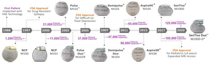
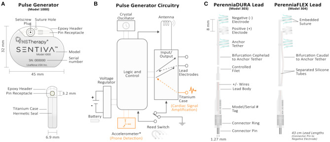
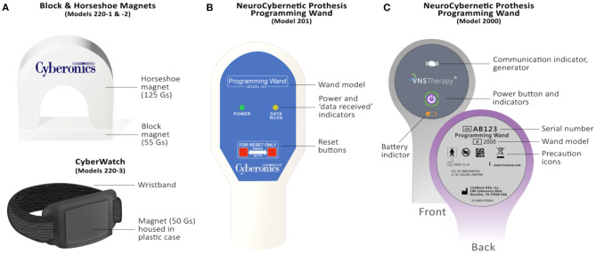
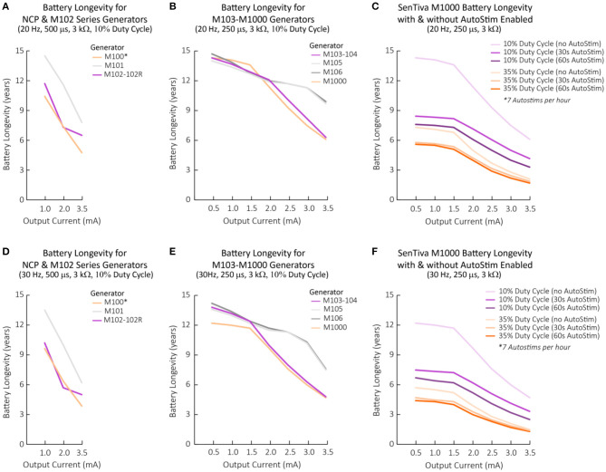
The vagus nerve stimulation (VNS) Therapy® System is the first FDA-approved medical device therapy for the treatment of drug-resistant epilepsy. Over the past two decades, the technology has evolved through multiple iterations resulting in software-related updates and implantable lead and generator hardware improvements. Healthcare providers today commonly encounter a range of single- and dual-pin generators (models 100, 101, 102, 102R, 103, 104, 105, 106, 1000) and related programming systems (models 250, 3000), all of which have their own subtle, but practical differences. It can therefore be a daunting task to go through the manuals of these implant models for comparison, some of which are not readily available. In this review, we highlight the technological evolution of the VNS Therapy System with respect to device approval milestones and provide a comparison of conventional open-loop vs. the latest closed-loop generator models. Battery longevity projections and an in-depth examination of stimulation mode interactions are also presented to further differentiate amongst generator models.

Keywords: VNS; drug-resistant epilepsy; medical device; neuromodulation; vagus nerve stimulation.


Conflict of interest statement

GW is an employee of LivaNova. PA and SA have participated in clinical trials for LivaNova. The remaining author declares that the research was conducted in the absence of any commercial or financial relationships that could be construed as a potential conflict of interest.

Figures

Figure 1
Figure 1
Evolution of the VNS therapy system. Timeline of VNS Therapy System generators with respect to FDA release year and cumulative patient implants worldwide (LivaNova, data on file). In 1988, the first patient was implanted with the VNS Therapy technology by neurologist James Kiffin Penry and neurosurgeon William Bell at the Wake-Forest Bowman Gray School of Medicine in the United States (46). Since then, 10 iterations of the VNS Therapy technology have been released for commercial use. The number of total worldwide patient implants (purple) is shown with respect to generator release year. The VNS Therapy received FDA approval in 1997 for use as an adjunctive therapy in reducing the frequency of partial onset seizures which are refractory to anti-seizure medications in adults and adolescents over 12 years of age. The technology's indication further expanded to include difficult-to-treat depression in 2005 and pediatrics (≥4 years) in 2017 (3). Expanded MRI access up to 3.0 Tesla imaging and allowing use of a transmit body coil for some generators also occurred in 2017 (5). *M1000-D generator is only licensed in Europe as of this review. HC, high capacity; M, model; MRI, magnetic resonance imaging; NCP, NeuroCybernetic Prosthesis; SR, sense and respond.
Figure 2
Figure 2
Technical overview of the VNS Therapy System's implantable components. (A) Front (top) and side (bottom) views of the M1000 implantable pulse generator. The generator circuitry is hermetically sealed in a titanium case. A hex screwdriver is inserted into the setscrew plug receptacle during surgery to secure the lead's connector pin upon insertion. Model and serial number information are printed on the front face of each generator. (B) Pulse generator circuitry schematic. The generator's circuitry includes, (1) crystal oscillator to provide a timing reference; (2) voltage regulator to regulate the system power supply from the battery; (3) antenna to receive programming signals and transmmit telemetry information to the Programming Wand; (4) logic and control that receives and implements programming commands, as well as collects and stores telemetry information (i.e., memory); (5) input/output controller to develop and modulate signals delivered to the lead. It can also allow the traditional VNS to serve as both therapy outputs and sensing inputs; (6) reed switch controlled by swiping the therapy's patient magent. For the M106, M1000, and M1000-D generators, the logic and control also processes sensory information (heart rate) and controls sensory-based therapy outputs (AutoStim). Components unique to the therapy's closed-loop generators (models 106, 1000, and 1000-D) are shown in orange. The input controller of closed-loop generators through the titanium case connection provides cardiac signal amplification. The accelerometer is unique to M1000 and M1000-D generators and provides information related to patient posture for prone event detection. (C) Single-pin PerenniaDURA M303 (left) and PerenniaFLEX M304 (right) implantable leads. Each lead features two active helical electrodes (negative and positive) that provides therapy output and a non-active anchor tether electrode used for stabalization purposes. Embedded sutures in the silicone casing of the helical eletrodes allows manipulation with forceps during surgery. The increased flexibility of the M304 lead is provided by the separated silicone tube configuration (right).
Figure 3
Figure 3
Overview of the VNS Therapy System's patient magnets and Programming Wands. (A) Legacy block (Model 220-1) & horseshoe (Model 220-2) magnets (top) and watch-style (Model 220-3) magnet (bottom). Guass (Gs), or magnetic flux density is provided for each magnet. (B) M201 Programming Wand. Light indicators on the front signify normal, successful communication (yellow DATA/RCVD light) and a good battery level (green POWER light). Compatible with the M250 “Motion Tablet” Programmer (not shown). The M201 Wand is turned on by pressing two red “RESET” buttons simultaneously. (C) Programming Wand M2000. The Wand's power button signifies whether it is powered on (two green lights below power button), connected to the M3000 Programmer (four green lights around power button), or is updating (green lights rotate around power button, v1.1+). Icons on the front of the Wand also signify communication with the generator (white flashing generator icon) and battery status (orange battery indicator if low). The back of the M2000 Wand features a serial number that registers on the M3000 Programmer for identification purposes.
Figure 4
Figure 4
Battery longevity projections for each VNS Therapy generator with respect to programmed stimulation settings. Battery longevity projections under various stimulation parameter settings calculated based on modeling from a generator's beginning of life until EOS (3, 23). (A–C) Battery longevity projections for generators programmed at 20 Hz with a typical lead impedance of 3 kΩ across varying output currents. Other stimulation parameters are displayed above the graph in brackets and in the legend, if applicable. (D–F) Battery longevity projections for generators programmed at 30 Hz with a typical lead impedance of 3 kΩ across varying output currents. Other stimulation parameters are displayed above the graph in brackets and in the legend, if applicable. (A,D) 500 μs was the lowest tested pulse width reported for NCP generators (23). 500 μs was used for M102 series generators for comparison purposes. For the M100 generator, calculations for serial numbers >10,000 were used. (C,F) The M1000 battery longevity with and without AutoStim enabled. Calculations based on 7 AutoStims per hour. Note that figure should not be used to exactly predict battery EOS but illustrates the effect of various parameters changes on battery life. AutoStim, autostimulation; EOS, end of service; M, model.
Figure 5
Figure 5
VNS Therapy stimulation mode interactions. (A) Interaction amongst stimulation modes during a therapy magnet swipe (purple icon). A magnet swipe interrupts both Normal Mode and AutoStim Mode stimulation (left). A magnet swipe during a Magnet Mode stimulation effectively resets the Magnet Mode stimulation period (right). Note the stimulation blackout time of 30 s to prevent overstimulation. (B) Interaction of stimulation modes with respect to tachycardia-triggered AutoStim Mode. Detected tachycardic events at varying AutoStim thresholds are shown superimposed upon an EKG trace. Because heartbeat sensing is disabled during a stimulation event, AutoStim Mode stimulation is not possible despite the heart rate surpassing the set AutoStim threshold (e.g., 40%). The Tachycardia Detection Algorithm is updated with heart rate information for 30s after stimulation. Also note the stimulation blackout time of 30s to prevent overstimulation where AutoStims cannot occur. Tachycardia detection, and therefore AutoStim is allowed after the blackout period. When a patient's relative heart rate surpasses the set AutoStim threshold (e.g., 40%) during an allowable time, AutoStim is triggered (right). Following an AutoStim event, an ‘enforced OFF time' equal to the length of the AutoStim event ensures a ≤ 50% duty cycle. Note that AutoStim Mode is only available on M106, M1000 and M1000-D generators. AutoStim, autostimulation; EKG, electrocardiogram; HR, heart rate.

References

    1. Morris GL, Mueller WM, Vagus Nerve Stimulation Study Group E01-E05 . Long-term treatment with vagus nerve stimulation in patients with refractory epilepsy. Neurology. (1999) 53:1731–35. 10.1212/WNL.53.8.1731 - DOI - PubMed
    1. Ben-Menachem E. Vagus nerve stimulation, side effects, and long-term safety. J Clin Neurophysiol. (2001) 18:415–18. 10.1097/00004691-200109000-00005 - DOI - PubMed
    1. LivaNova Inc . VNS Therapy Physician's Manual. LivaNova, Inc., 26-0009-7600/6 (U.S.) (2020).
    1. Arle JE. New vagus nerve stimulation lead and implantable pulse generator placement. In: Arle JE, editor, The Neuromodulation Casejournal. Cambridge, MA, Academic Press; (2020). p. 153–8. 10.1016/B978-0-12-817002-1.00020-1 - DOI
    1. LivaNova Inc . MRI with the VNS Therapy® System. LivaNova, Inc., 26-0010-0300/2 (worldwide) (2019).