. 2022 Jan 21;375(6578):eabj7662.
doi: 10.1126/science.abj7662. Epub 2022 Jan 21.

Reconfigurable asymmetric protein assemblies through implicit negative design

Affiliations

Reconfigurable asymmetric protein assemblies through implicit negative design

Danny D Sahtoe et al. Science. .

Abstract

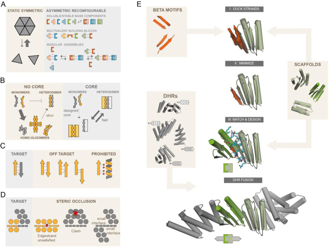
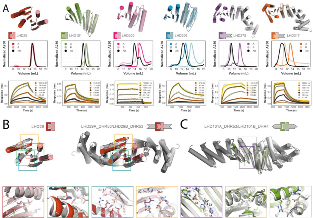
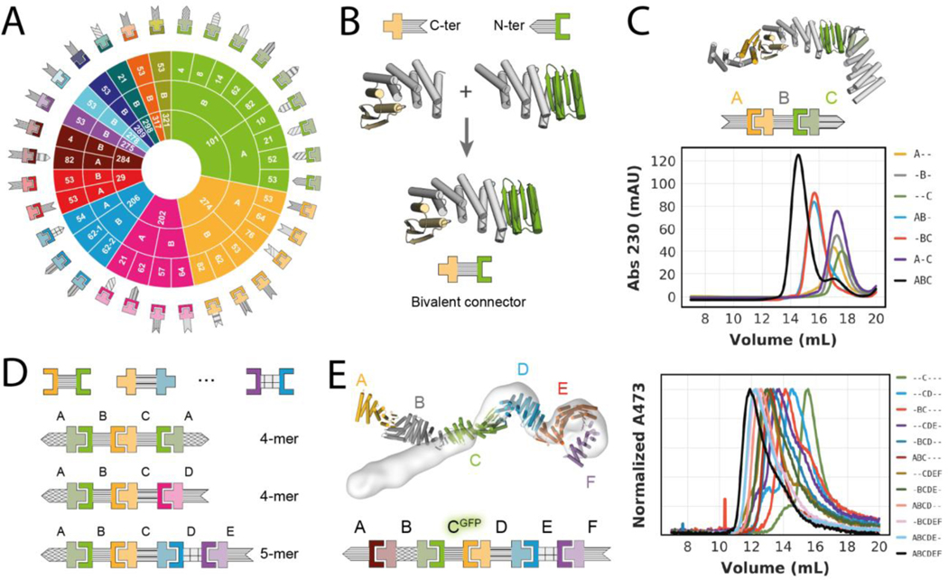
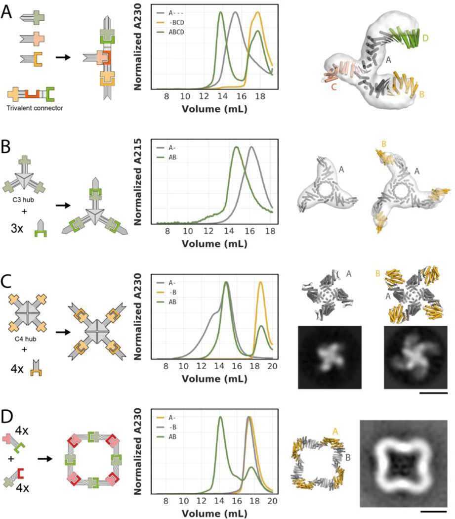
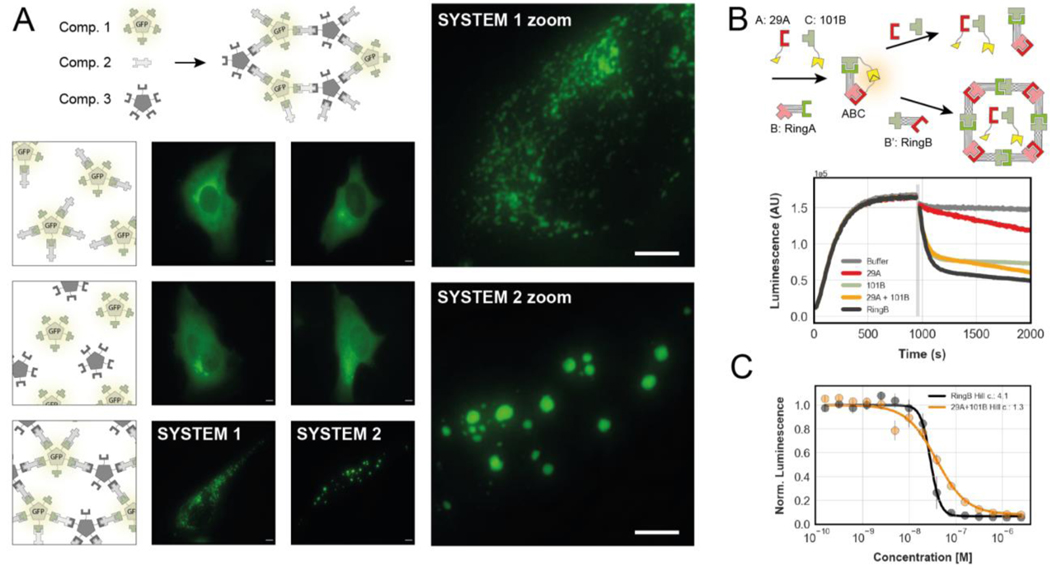
Asymmetric multiprotein complexes that undergo subunit exchange play central roles in biology but present a challenge for design because the components must not only contain interfaces that enable reversible association but also be stable and well behaved in isolation. We use implicit negative design to generate β sheet-mediated heterodimers that can be assembled into a wide variety of complexes. The designs are stable, folded, and soluble in isolation and rapidly assemble upon mixing, and crystal structures are close to the computational models. We construct linearly arranged hetero-oligomers with up to six different components, branched hetero-oligomers, closed C4-symmetric two-component rings, and hetero-oligomers assembled on a cyclic homo-oligomeric central hub and demonstrate that such complexes can readily reconfigure through subunit exchange. Our approach provides a general route to designing asymmetric reconfigurable protein systems.


Figures

Fig. 1.
Fig. 1.. Strategies for the design of asymmetric hetero-oligomeric complexes.
(A) Many design efforts have focused on cooperatively assembling symmetric complexes (left) with little subunit exchange. Here we sought to create asymmetric hetero-oligomers from stable heterodimeric building blocks, that can modularly exchange subunits (right). (B,C,D) Schematic illustration of properties that can contribute to preventing self-association. (B) Protomers that have a substantial hydrophobic core (right rectangles) are less likely to form stable homo-oligomers than protomers of previously designed heterodimers lacking hydrophobic monomer cores. (C) In beta-sheet extended interfaces, most homodimer states that bury non h-bonding polar edge strand atoms are energetically inaccessible. Potential homodimers are more likely to form via beta sheet extension. These are restricted to only 2 orientations (parallel and antiparallel) and a limited number of offset registers. Arrows and ribbons represent strands and helices, respectively; thin lines indicate hydrogen bonds, red stars indicate unsatisfied polar groups. (D) “Cross sectional” schematic view (helices as circles, beta strands as rectangles, star indicates steric clash) By modeling the limited number of beta sheet homodimers across the beta edge strand, structural elements may be designed that specifically block homodimer formation or make it unlikely due to small interfaces, but still allow heterodimer formation. (E) Design workflow: Beta sheet motifs are docked to the edge strands of a library of hydrophobic core containing (modified) fold-it scaffolds. Minimized docked strands are incorporated into the scaffolds by matching the strands to the scaffold library, yielding docked protein-protein complexes, followed by interface sequence design. Resulting docks are fused rigidly on their terminal helices to a library of DHRs.
Fig 2.
Fig 2.. Designed heterodimer characterization.
(A) Top row, design models of six different heterodimers. Coloring of heterodimer schematics is maintained throughout the paper. Middle row, normalized SEC traces of individual protomers (A, B) and complexes (AB). Bottom row, kinetic binding traces with global kinetic fits of in vitro biolayer interferometry binding assays. (B) and (C): Crystal structures (in colors) of the designs LHD29, LHD29A53/B53 and LHD101A53/B4 overlayed on design models (light gray). Colored rectangles in the full models (top row) match the corresponding detailed views (bottom row). Sequences and models for all proteins can be found in the Supplementary excel file.
Fig. 3.
Fig. 3.. Design of higher order assemblies.
(A) Schematic overview of experimentally validated heterodimer-DHR fusions. Inner ring represents the heterodimer, middle ring the protomer chain that is fused, and outer ring the DHR (28) fusion partner. Patterning of DHR schematic is consistent throughout the paper. (B) Schematic representation of the design-free alignment method used to generate bivalent connectors from rigid fusions shown in A. Top left: LHD274B fused to the N-terminus of DHR53 (274B53), Top right: LHD101A fused to the C-terminus of DHR53 (101A53), bottom: Bivalent connector DFB0. (C) Top: Design model and schematic representation of a heterotrimer comprising the bivalent connector shown in B (“B”), and two of the rigid fusions shown in A (“A” = 274A53; “C” = 101B62). Bottom: SEC traces for all possible combinations of the trimer components. (D) Schematic representations of 3 examples of bivalent connectors (see Fig. S10A for full list) that were generated as shown in B and schematic representation of experimentally validated higher order assemblies (see Fig. S10 and S11). (E) Left: overlay of heterohexamer design model (in colors) and nsEM density (light grey). Right: SEC traces of partial and full mixtures of the hexamer components (“A” = 284A82, “B” = DF284, “C” = DFA-GFP, “D” = DF206, “E” = DF275A, “F”=275B). Absorbance was monitored at 473 nm to follow the GFP-tagged component C. Sequences, models and chain-to-construct mapping can be found in the Supplementary excel file. Affinities of individual interactions can be found in Supplementary tables S1 and S3. Mapping of schemes to names for individual components can be found in Fig. S25.
Fig. 4.
Fig. 4.. Design of branched and closed hetero-oligomeric assemblies.
(A) Left: Schematic representation of a trivalent connector (“A” = TF10) that can bind three different binding partners (“B” = 274A53, ”C” = 317B, “D” = 101B62). Center: SEC analysis of the trivalent connector, the binding partners, and the full assembly mixture. Right: Overlay of design model (in colors) and nsEM density (light grey) of the complex formed by the trivalent connector and all three binding partners. (B) From left to right: : Schematic representation of a C3-symmetric “hub” presenting three copies of LHD101B; SEC analysis of the C3-symmetric “hub” without (“A-”) and with (“AB”) its cognate binding partner (“B” = 101A53); overlay of design model (dark grey) and nsEM density (light grey) of the C3-symmetric “hub”; overlay of design model (dark grey and gold) and nsEM density (light grey) of the C3-symmetric “hub” bound to three copies of its binding partner. (C): From left to right: : Schematic representation of a C4-symmetric “hub” presenting four copies of LHD274B; SEC analysis of the C4-symmetric “hub” without (“A-”) and with (“AB”) its cognate binding partner (274A53); design model (top) and representative nsEM class average (bottom) of the C4-symmetric “hub”; design model (top) and representative nsEM class average (bottom) of the C4-symmetric “hub” bound to 4 copies of the binding partner. (D) From left to right: Schematic representation of a C4-symmetric closed ring comprising two components (“A” and “B”); SEC analysis of the individual ring components (“A-” and “-B”) and the stoichiometric mixture (“AB”); design model of the C4-symmetric ring; representative nsEM class average. Scale bars: 10 nm.
Fig. 5.
Fig. 5.. Inducible and reconfigurable assemblies.
(A) Cross-linking of homo-pentamers by bivalent connectors in cells. Top: Schematic representation of components. Bottom: schematic representations (1st column) and fluorescence microscopy images (2nd and 3rd columns) of cells expressing different combinations of components. High affinity system 1 (2nd column) uses LHD101 and LHD275; low affinity system 2 (3rd column) uses LHD101 and LHD321. See Fig. S22 for additional control images. Scale bars: 5 μm. (B) Top: schematic representation of an “ABC” heterotrimer with split luciferase activity (yellow shapes) undergoing subunit exchange through addition of non-luciferase tagged components. Bottom: Real-time luminescence measurement of samples containing the mixture “ABC” shown on the top left. Grey bar indicates addition of either buffer (grey trace) or non-luciferase tagged components LHD29A and LHD101B. (C) Titration of either component RingB or non-luciferase tagged components LHD29A and LHD101B to the preformed ABC heterotrimer. Data fitted to the hill equation. Error bars represent sd.

References

    1. Tusk SE, Delalez NJ, Berry RM, Subunit Exchange in Protein Complexes. J. Mol. Biol 430, 4557–4579 (2018). - PubMed
    1. Engel C, Neyer S, Cramer P, Distinct Mechanisms of Transcription Initiation by RNA Polymerases I and II. Annu. Rev. Biophys 47, 425–446 (2018). - PubMed
    1. Burgers PMJ, Kunkel TA, Eukaryotic DNA Replication Fork. Annu. Rev. Biochem 86, 417–438 (2017). - PMC - PubMed
    1. Gonen S, DiMaio F, Gonen T, Baker D, Design of ordered two-dimensional arrays mediated by noncovalent protein-protein interfaces. Science. 348, 1365–1368 (2015). - PubMed
    1. Hsia Y, Bale JB, Gonen S, Shi D, Sheffler W, Fong KK, Nattermann U, Xu C, Huang P-S, Ravichandran R, Yi S, Davis TN, Gonen T, King NP, Baker D, Design of a hyperstable 60-subunit protein dodecahedron. [corrected]. Nature. 535, 136–139 (2016). - PMC - PubMed

Publication types