Review
. 2022 Jan 11;14(2):286.
doi: 10.3390/polym14020286.

Cellulose-Based Nanofibers Processing Techniques and Methods Based on Bottom-Up Approach-A Review

Affiliations
Review

Cellulose-Based Nanofibers Processing Techniques and Methods Based on Bottom-Up Approach-A Review

Ana Kramar et al. Polymers (Basel). .

Abstract

In the past decades, cellulose (one of the most important natural polymers), in the form of nanofibers, has received special attention. The nanofibrous morphology may provide exceptional properties to materials due to the high aspect ratio and dimensions in the nanometer range of the nanofibers. The first feature may lead to important consequences in mechanical behavior if there exists a particular orientation of fibers. On the other hand, nano-sizes provide a high surface-to-volume ratio, which can have important consequences on many properties, such as the wettability. There are two basic approaches for cellulose nanofibers preparation. The top-down approach implies the isolation/extraction of cellulose nanofibrils (CNFs) and nanocrystals (CNCs) from a variety of natural resources, whereby dimensions of isolates are limited by the source of cellulose and extraction procedures. The bottom-up approach can be considered in this context as the production of nanofibers using various spinning techniques, resulting in nonwoven mats or filaments. During the spinning, depending on the method and processing conditions, good control of the resulting nanofibers dimensions and, consequently, the properties of the produced materials, is possible. Pulp, cotton, and already isolated CNFs/CNCs may be used as precursors for spinning, alongside cellulose derivatives, namely esters and ethers. This review focuses on various spinning techniques to produce submicrometric fibers comprised of cellulose and cellulose derivatives. The spinning of cellulose requires the preparation of spinning solutions; therefore, an overview of various solvents is presented showing their influence on spinnability and resulting properties of nanofibers. In addition, it is shown how bottom-up spinning techniques can be used for recycling cellulose waste into new materials with added value. The application of produced cellulose fibers in various fields is also highlighted, ranging from drug delivery systems, high-strength nonwovens and filaments, filtration membranes, to biomedical scaffolds.

Keywords: cellulose; cellulose derivatives; nanofibers; spinning techniques.


Conflict of interest statement

The authors declare no conflict of interest.

Figures

Figure 1
Figure 1
Number of publications per year from database Scopus using keywords “cellulose” and “nanofibers” (left) and refined search including the word “spinning” (right).
Figure 2
Figure 2
Chemical structure of cellulose.
Figure 3
Figure 3
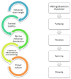
Some important properties of polymers for ensuring spinnability and simplified scheme of steps during spinning.
Figure 4
Figure 4
Scheme of the electrospinning system used for production of cellulose fibers (reprinted from Polymer. 2006, 47, 5097–5107, Kim, C.W.; Kim, D.S.; Kang, S.Y.; Marquez, M.; Joo, Y.L. Structural studies of electrospun cellulose nanofibers, with permission from Elsevier).
Figure 5
Figure 5
A scheme of the preparation of all-cellulose composite nanofibers from the same source using electrospinning and its potential use as scaffolds (reprinted with permission from He, X.; Xiao, Q.; Lu, C.; Wang, Y.; Zhang, X.; Zhao, J.; Zhang, W.; Zhang, X.; Deng, Y. Uniaxially aligned electrospun all-cellulose nanocomposite nanofibers reinforced with cellulose nanocrystals: Scaffold for tissue engineering. Biomacromolecules 2014, 15, 618–627. Copyright (2014), American Chemical Society).
Figure 6
Figure 6
Cellulose contained in plants has a hierarchical structure from the meter to nanometer scale (reprinted with permission of authors from reference [67]).
Figure 7
Figure 7
Dry-wet solution blow spinning of cellulose fibers from solution in ionic liquid (reprinted from reference Jedvert, K.; Idström, A.; Köhnke, T.; Alkhagen, M. Cellulosic nonwovens produced via efficient solution blowing technique. J. Appl. Polym. Sci. 2020, 48339, 1–9).
Figure 8
Figure 8
Schematic representation of wet solution blow spinning apparatus of cellulose fibers with mist coagulation chamber (left) and dependency of fiber diameter on air velocity during solution blow spinning (reprinted from the European Polymer Journal, 2020, 125, 109513, Zhang, J.; Kitayama, H.; Gotoh, Y. High strength ultrafine cellulose fibers generated by solution blow spinning, with permission from Elsevier).
Figure 9
Figure 9
(left) Wet spinning of CNFs. (a) Wet-spinning setup using controlled extrusion with a syringe pump into a THF coagulation bath using NFC and NFCh dispersions, containing surface modifications as depicted in (b) and (c). (dg) AFM height images for NFC (d) and NFCh (g), as well as their corresponding image analysis concerning the average height of 200 nanofibrils for each class of nanoparticle ((e) = NFC; (f) = NFCh); (right) schematic drawing for the computer-controlled wet-stretching device into which a fiber can be clamped and immersed into a liquid and stretched using controlled strain rates (reprinted with permission from Torres-Rendon, J.G.; Schacher, F.H.; Ifuku, S.; Walther, A. Mechanical performance of macrofibers of cellulose and chitin nanofibrils aligned by wet-stretching: A critical comparison. Biomacromolecules 2014, 15, 2709–2717. Copyright 2014, American Chemical Society).
Figure 10
Figure 10
General scheme of dry-jet wet spinning using air gap between spinneret and coagulation bath (reprinted from International Journal of Biological Micromolecules, 2016, 92, 1197–1204, Boy, R.; Narayanan, G.; Chung, C.C.; Kotek, R. Novel cellulose-collagen blend biofibers prepared from an amine/salt solvent system, with permission from Elsevier).
Figure 11
Figure 11
Scheme showing all stages during dry-wet spinning process (reprinted from Polymer, 2013, 54, 935–914, Endo, R.; Saito, T.; Isogai, A. TEMPO-oxidized cellulose nanofibril/poly(vinyl alcohol) composite drawn fibers, with permission from Elsevier).
Figure 12
Figure 12
Schematic representation of (a) process of IPC of TOCN/polycation fibers, and (b) suggested cross-section of formed wet filament with polycation containing solution on the periphery and the formed polyelectrolyte complex membrane at the interface of the two fluids (Reprinted from reference Toivonen, M.S.; Kurki-Suonio, S.; Wagermaier, W.; Hynninen, V.; Hietala, S.; Ikkala, O. Interfacial Polyelectrolyte Complex Spinning of Cellulose Nanofibrils for Advanced Bicomponent Fibers. Biomacromolecules 2017, 18, 1293–1301, Copyright 2017, American Chemical Society).
Figure 13
Figure 13
A scheme of triaxial electrospinning (a); triaxial spinneret (b); tricomponent fiber (c); scheme of the concept for triaxial spinning (d); application of tricomponent fiber for sustainable drug release (e) (reprinted and adapted from Carbohydrate Polymers, 2020, 243, 116477, Yang, Y.; Chang, S.; Bai, Y.; Du, Y.; Yu, D.G. Electrospun triaxial nanofibers with middle blank cellulose acetate layers for accurate dual-stage drug release, with permission from Elsevier).
Figure 14
Figure 14
Schematic diagram of preparation of cellulose membrane via electrospinning of cellulose acetate with TiO2 nanoparticles and rectorite, followed by deacetylation to pure cellulose with increased absorption properties towards heavy metal ions Pb2+, Cu2+ and Cd2+ (reprinted from International Journal of Biological Macromolecules 2021, 183, 245–253, Wang, C.; Zhan, Y.; Wu, Y.; Shi, X.; Du, Y.; Luo, Y.; Deng, H. TiO2/rectorite-trapped cellulose composite nanofibrous mats for multiple heavy metal adsorption, with permission from Elsevier).
Figure 15
Figure 15
Scheme or rotary jet spinning (a); resulting cellulose acetate spun membrane (b); different morphology observed by SEM of fibers with various concentrations of CA and soy protein SPH (ch) (reprinted from Advanced Healthcare Materials, 2018, 7, 1–13, Ahn, S.; Chantre, C.O.; Gannon, A.R.; Lind, J.U.; Campbell, P.H.; Grevesse, T.; O’Connor, B.B.; Parker, K.K. Soy Protein/Cellulose Nanofiber Scaffolds Mimicking Skin Extracellular Matrix for Enhanced Wound Healing, with permission from John Wiley & Sons, Inc.).
Figure 16
Figure 16
Example of the degree of substitution (DS) (e.g., 3) and molecular substitution (MS) (e.g., 6) on one anhydroglucose unit (AGU) of hydroxyethylcellulose.
Figure 17
Figure 17
(a) Scheme of triaxial electrospinning; (b) kinetic profile of ketoprofen release over time from tiraxialy electrospun fibers; (c) cross sectional morphology of triaxial fibers and (d) digital photograph of triaxial electrospinning process (reprinted and adapted from Applied Materials and Interfaces, 2015, 7, 33, 18891–18897, Yu, D.G.; Li, X.Y.; Wang, X.; Yang, J.H.; Bligh, S.W.A.; Williams, G.R. Nanofibers Fabricated Using Triaxial Electrospinning as Zero Order Drug Delivery Systems, Copyright 2015, American Chemical Society).
Figure 18
Figure 18
(a) Schematic diagram of modified coaxial electrospinning; (b) photograph of homemade concentric spinneret and (c) the proposed mechanism of nanofibers formation using sheath solvent in coaxial electrospinning (reprinted from reference [171]).
Figure 19
Figure 19
(a) Experimental apparatus of side-by-side electrospinning process; (b) photograph of typical side-by-side electrospinning process; (c) Janus Taylor cone formed with Teflon-coated spinneret; (d) mat of fibers produced using non-coated side-by-side spinneret; (e) separation of fluids when using non-coated side-by-side spinneret and (f) illustration of the influence of Teflon-coated spinneret: A separation of fluids arising from repulsive forces and B formation of the integrated Janus Taylor cone with the Teflon coating (reprinted from reference [174] with permission from Elsevier).
Figure 20
Figure 20
FESEM images of the fibers remaining after 24 h of dissolution (ad) and proposed mechanism of drug release from Janus fibers (e) (reprinted from reference [174] with permission from Elsevier).
Figure 21
Figure 21
Graphical representation of the preparation of nanofibers and drug tetracycline hydrochloride (TCH) using (a) coaxial electrospinning and (b) blend electrospinning (reprinted from Materials Science and Engineering C, 2017, 77, 1117–1127, Esmaeili, A.; Haseli, M. Electrospinning of thermoplastic carboxymethyl cellulose/poly(ethylene oxide) nanofibers for use in drug-release systems, with permission from Elsevier).

References

    1. Klemm D., Philipp B., Heinze T., Heinze U., Wagenknecht W. Comprehensive Cellulose Chemistry Volume l Fundamentals and Analytical Methods. Volume 1. Wiley-VCH; Weinheim, Germany: 1998.
    1. Ibrahim H.M., Klingner A. A review on electrospun polymeric nanofibers: Production parameters and potential applications. Polym. Test. 2020;90:106647. doi: 10.1016/j.polymertesting.2020.106647. - DOI
    1. Thenmozhi S., Dharmaraj N., Kadirvelu K., Kim H.Y. Electrospun nanofibers: New generation materials for advanced applications. Mater. Sci. Eng. B Solid-State Mater. Adv. Technol. 2017;217:36–48. doi: 10.1016/j.mseb.2017.01.001. - DOI
    1. Barhoum A., Pal K., Rahier H., Uludag H., Kim I.S., Bechelany M. Nanofibers as new-generation materials: From spinning and nano-spinning fabrication techniques to emerging applications. Appl. Mater. Today. 2019;17:1–35. doi: 10.1016/j.apmt.2019.06.015. - DOI
    1. Bachs-Herrera A., Yousefzade O., Del Valle L.J., Puiggali J. Melt electrospinning of polymers: Blends, nanocomposites, additives and applications. Appl. Sci. 2021;11:1808. doi: 10.3390/app11041808. - DOI

LinkOut - more resources