Review
. 2021 Dec 29;25(1):103708.
doi: 10.1016/j.isci.2021.103708. eCollection 2022 Jan 21.

Toroidal electromagnetically induced transparency based meta-surfaces and its applications

Affiliations
Review

Toroidal electromagnetically induced transparency based meta-surfaces and its applications

Angana Bhattacharya et al. iScience. .

Abstract

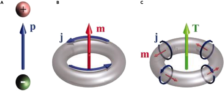
The vigorous research on low-loss photonic devices has brought significance to a new kind of electromagnetic excitation, known as toroidal resonances. Toroidal excitation, possessing high-quality factor and narrow linewidth of the resonances, has found profound applications in metamaterial (MM) devices. By the coupling of toroidal dipolar resonance to traditional electric/magnetic resonances, a metamaterial analogue of electromagnetically induced transparency effect (EIT) has been developed. Toroidal induced EIT has demonstrated intriguing properties including steep linear dispersion in transparency windows, often leading to elevated group refractive index in the material. This review summarizes the brief history and properties of the toroidal resonance, its identification in metamaterials, and their applications. Further, numerous theoretical and experimental demonstrations of single and multiband EIT effects in toroidal-dipole-based metamaterials and its applications are discussed. The study of toroidal-based EIT has numerous potential applications in the development of biomolecular sensing, slow light systems, switches, and refractive index sensing.

Keywords: Applied sciences; Engineering; Photonics.


Conflict of interest statement

The authors declare no competing interests.

Figures

Figure 1
Figure 1
The formation of electric, magnetic, and toroidal dipolar moments (A) Electric dipolar moment is formed because of charge separation. (B) Magnetic moment formation because of the flow of current along a circular loop. (C) Toroidal moment formation because of the poloidal currents flowing along the arms of a torus. From (Kaelberer et al., 2010). Reprinted with permission from The American Association for the Advancement of Science.
Figure 2
Figure 2
Experimental demonstration of toroidal excitation in metamaterials (A) Experimental setup of toroidal excitation achieved in the gigahertz regime for a MM design consisting of 3D loops of resonators. (B) Arrangement of magnetic moments ‘m'at resonance termed as I. (C) Head-to-tail arrangement of magnetic moments at resonance II, leading to the excitation of toroidal dipole moment along the z-direction. (D) Transmission spectrum of the MM depicting the origins of the two resonances. (E) Reflection spectrum of the MM with calculated Q factors of the resonances. From (Kaelberer et al., 2010). Reprinted with permission from The American Association for the Advancement of Science.
Figure 3
Figure 3
Toroidal resonance in a planar metamaterial geometry (A) Planar MM geometry exhibiting toroidal excitation via oppositely circulating current in the SRR arms. The orientation of surface current excites toroidal dipole moment along the blue arrow in the plane of the geometry. (B) Head-to-tail orientation of magnetic dipole moments indicating toroidal signature. Adapted with permission from ref (Gupta et al., 2016), John Wiley and Sons.
Figure 4
Figure 4
Refractive index sensing via a planar toroidal MM (A) Schematic of the MM. (B) The fabricated sample of the MM. (C) The surface current profile of the MM geometry. (D) Analyte of thickness ‘t'placed over the MM sample for refractive index sensing. (E) The transmission spectrum shows a red-shift on placing a layer of analyte (photoresist) over the two-dimensional toroidal MM. (F)The shift in resonance for Tx component of toroidal moment. Reproduced from (Gupta et al., 2017), with the permission of AIP Publishing.
Figure 5
Figure 5
Application of toroidal excitation in a metamaterial based switch (A) Dynamic switching from toroidal dipole mode in the MM to magnetic and electric dipole mode via photoexcitation of silicon pads embedded in capacitive gaps. (B) Surface current profiles of the planar MM geometry showing alignment of magnetic moments in opposite directions in toroidal dipolar configuration. (C) Magnetic moments aligned along the same direction, indicating switching behavior from toroidal to magnetic mode. (D) Surface current profile for toroidal mode in the MM configuration where Si pads are inserted in both gaps. (E) Switching from toroidal mode to electric dipolar mode, depicted via surface current profile. Adapted with permission from ref (Gupta et al., 2018)., John Wiley and Sons.
Figure 6
Figure 6
Active tuning of toroidal excitation in a terahertz metamaterial (A) Schematic of the proposed MM. (B) Transmission profile of the MM derived experimentally and via simulation. (C) The multipolar analysis evaluates the power scattered by the five major electromagnetic moments. Toroidal power scattered dominates over scattered power of other electromagnetic moments. (D) Experimental and numerical tuning of the transmission amplitude by varying the AC conductivity of graphene. Reprinted (adapted) with permission from (Ahmadivand et al., 2019). Copyright 2019 American Chemical Society.
Figure 7
Figure 7
Toroidal excitation based EIT in MMs (A) Schematic of the toroidal based-EIT MM.b) Resonance frequencies of dark and bright mode with corresponding surface current profile and magnetic field profile. (B) The transmission profile of the MM array demonstrating single band EIT. (C) Simulated and experimentally obtained transmission spectrum for the combined MM geometry. (D) Fano resonance excitation for symmetric configuration of MM.Inset indicates MM geometry. (E) EIT response of transmission spectrum for increasing asymmetry. (F)Magnetic field profile of toroidal excitation. (G) Schematic for single band EIT MM. (H) Corresponding transmission profile of the single band EIT. (I) Surface current profile at EIT peak. (J) Schematic of asymmetric E type SRR and cut wire based MM geometry. (K) Excitation of single band EIT. l) Multipolar analysis of the corresponding geometry. Figures 7A–7C) Reproduced from Ref(JunáHe et al., 2017). with permission from the Royal Society of Chemistry, Figures 7D–7Ff). Adapted with permission from (Han et al., 2018)© The Optical Society, Figures 7G–7I). Reprinted from (Li et al., 2015), with the permission of AIP Publishing., Figures 7J–7L) Adapted from (Shen et al., 2020) with full permission.
Figure 8
Figure 8
Actively tunable toroidal based EIT for an all dielectric metasurface made of silicon nano-cuboids with a active tuning enabled via a graphene layer (A) Schematic of the all dielectric metasurface. (B) Transmission spectrum for different values of Fermi energy. (C) Multipolar analysis of the MM geometry (Sun et al., 2020).
Figure 9
Figure 9
Demonstration of single band EIT in a toroidal terahertz metamaterial (A) Schematic of the toroidal based single-band EIT MM in the THz range. The incident THz field is polarized parallel to the split gap i.e., along y axis. (B) The transmission profile of the proposed MM array demonstrating single band EIT. (C) Electric field profiles at 0.97 THz (dip 1), at the peak frequency of 1.02 THz and at 1.05 THz (dip 2).
Figure 10
Figure 10
Multiband EIT in toroidal MM (A) Schematic of the 3D MM geometry consisting of 12-fold double metal bars and a rod demonstrating EIT in the optical range. (B) The corresponding transmission profile of the MM array for increasing asymmetry along the x direction. (C) Schematic of double sided toroidal planar MM demonstrating dual EIT in the microwave range. (D) Corresponding transmission profile of the MM geometry. Figures 10A and 10B. Reprinted from (Li et al., 2016), with the permission of AIP Publishing. Figures 10C and 10D (Lei et al., 2021) Copyright (2021) The Japan Society of Applied Physics
Figure 11
Figure 11
Multiband toroidal excitation based EIT in terahertz metamaterial (A) Schematic of the toroidal metamaterial design exhibiting multiband EIT phenomenon. The incident THz field is polarized parallel to the split gap i.e., along y axis. (B) Magnified view of the unit cell of the MM. ‘Px’, ‘Py’are the periodicities of the unit cell. Split gaps are denoted by ‘g1’and ‘g2’. The length of mid SRR (TSRR) is ‘L'and that of the other C shaped SRRs (CSRR) is ‘L1’.The distance of each CSRR from the mid TSRR is termed as ‘d’. (C) Transmission spectra showing multiband transparency effect for ‘d’ = 10 μm. (C) The electric field profile at the first peak P1. (D) The electric field profile at the second peak P2. Transmission spectrum for different values of distance ‘d’, which signifies the distance between adjacent resonators in our proposed MM geometry, i.e., d = 5 μm. (E), d = 10 μm. (F), and d = 15 μm. (G). A blue shift is observed on changing ‘d'from 5 μm to 15 μm which may be attributed to the reduced coupling between the resonators on increasing d (Bhattacharya et al., 2021).
Figure 12
Figure 12
Applications of EIT based toroidal MMs (A) Variation of effective refractive index with wavelength for ’E’ shaped resonator. (B) Variation of group index with asymmetry parameter. (C) Variation of group index with frequency for a toroidal EIT MM in the GHz regime. (D) Sensing application of the MM showing transmission spectra for varying refractive index of the surrounding medium. (E) Numerically calculated transmission spectra for different refractive index (n) of analyte coated on the top of the proposed MM. (F) The shift in frequency for the second and third transmission dips with varying refractive index of the analyte. Figures 12A and B Adapted with permission from (Han et al., 2018)© The Optical Society. Figures 12C and D Adapted from (Shen et al., 2020) with full permission.

Similar articles

Cited by

References

    1. Ahmadivand A., Gerislioglu B., Manickam P., Kaushik A., Bhansali S., Nair M., Pala N. Rapid detection of infectious envelope proteins by magnetoplasmonic toroidal metasensors. ACS Sens. 2017;2:1359–1368. - PubMed
    1. Ahmadivand A., Gerislioglu B., Tomitaka A., Manickam P., Kaushik A., Bhansali S., Nair M., Pala N. Extreme sensitive metasensor for targeted biomarkers identification using colloidal nanoparticles-integrated plasmonic unit cells. Biomed. Opt. Express. 2018;9:373–386. - PMC - PubMed
    1. Ahmadivand A., Gerislioglu B., Noe G.T., Mishra Y.K. Gated graphene enabled tunable charge–current configurations in hybrid plasmonic metamaterials. ACS Appl. Electron. Mater. 2019;1:637–641.
    1. Ahmadivand A., Gerislioglu B., Ahuja R., Mishra Y.K. Terahertz plasmonics: the rise of toroidal metadevices towards immunobiosensings. Mater. Today. 2020;32:108–130.
    1. Baryshnikova K.V., Smirnova D.A., Luk’yanchuk B.S., Kivshar Y.S. Optical anapoles: concepts and applications. Adv. Opt. Mater. 2019;7:1801350.

LinkOut - more resources