

ConGen-A Simulator-Agnostic Visual Language for Definition and Generation of Connectivity in Large and Multiscale Neural Networks
- PMID: 35069166
- PMCID: PMC8777257
- DOI: 10.3389/fninf.2021.766697
ConGen-A Simulator-Agnostic Visual Language for Definition and Generation of Connectivity in Large and Multiscale Neural Networks
Abstract
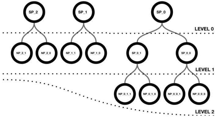
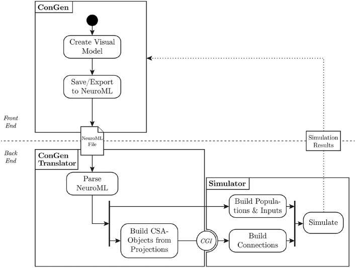
An open challenge on the road to unraveling the brain's multilevel organization is establishing techniques to research connectivity and dynamics at different scales in time and space, as well as the links between them. This work focuses on the design of a framework that facilitates the generation of multiscale connectivity in large neural networks using a symbolic visual language capable of representing the model at different structural levels-ConGen. This symbolic language allows researchers to create and visually analyze the generated networks independently of the simulator to be used, since the visual model is translated into a simulator-independent language. The simplicity of the front end visual representation, together with the simulator independence provided by the back end translation, combine into a framework to enhance collaboration among scientists with expertise at different scales of abstraction and from different fields. On the basis of two use cases, we introduce the features and possibilities of our proposed visual language and associated workflow. We demonstrate that ConGen enables the creation, editing, and visualization of multiscale biological neural networks and provides a whole workflow to produce simulation scripts from the visual representation of the model.
Keywords: connectivity generation; connectome; large scale simulation; multiscale simulation; neural networks; visual language.
Copyright © 2022 Herbers, Calvo, Diaz-Pier, Robles, Mata, Toharia, Pastor, Peyser, Morrison and Klijn.
Conflict of interest statement
The authors declare that the research was conducted in the absence of any commercial or financial relationships that could be construed as a potential conflict of interest.
Figures


Similar articles
-
Efficient generation of connectivity in neuronal networks from simulator-independent descriptions.Front Neuroinform. 2014 Apr 22;8:43. doi: 10.3389/fninf.2014.00043. eCollection 2014. Front Neuroinform. 2014. PMID: 24795620 Free PMC article.
-
Visually defining and querying consistent multi-granular clinical temporal abstractions.Artif Intell Med. 2012 Feb;54(2):75-101. doi: 10.1016/j.artmed.2011.10.004. Epub 2011 Dec 15. Artif Intell Med. 2012. PMID: 22177662
-
Mapping brain-behavior networks using functional and structural connectome fingerprinting in the HCP dataset.Brain Behav. 2020 Jun;10(6):e01647. doi: 10.1002/brb3.1647. Epub 2020 Apr 30. Brain Behav. 2020. PMID: 32351025 Free PMC article.
-
Plant multiscale networks: charting plant connectivity by multi-level analysis and imaging techniques.Sci China Life Sci. 2021 Sep;64(9):1392-1422. doi: 10.1007/s11427-020-1910-1. Epub 2021 Mar 12. Sci China Life Sci. 2021. PMID: 33974222 Review.
-
Harmonic Brain Modes: A Unifying Framework for Linking Space and Time in Brain Dynamics.Neuroscientist. 2018 Jun;24(3):277-293. doi: 10.1177/1073858417728032. Epub 2017 Sep 1. Neuroscientist. 2018. PMID: 28863720 Review.
References
-
- Abi Akar N., Biddiscombe J., Cumming B., Huber F., Kabic M., Karakasis V., et al. . (2021). arbor-sim/arbor: Arbor library v0.5.
-
- Akar N. A., Cumming B., Karakasis V., Kusters A., Klijn W., Peyser A., et al. . (2019). “Arbor–a morphologically-detailed neural network simulation library for contemporary high-performance computing architectures,” in 2019 27th Euromicro International Conference on Parallel, Distributed and Network-Based Processing (PDP) (Pavia), 274–282. 10.1109/EMPDP.2019.8671560 - DOI - PubMed
-
- Cakan C., Jajcay N., Obermayer K. (2021). neurolib: a simulation framework for whole-brain neural mass modeling. bioRxiv. 10.1007/s12559-021-09931-9 - DOI
LinkOut - more resources
Full Text Sources