Review
. 2022 Feb 23;122(4):4356-4396.
doi: 10.1021/acs.chemrev.1c00685. Epub 2022 Jan 28.

Semiconducting Polymers for Neural Applications

Affiliations
Review

Semiconducting Polymers for Neural Applications

Ivan B Dimov et al. Chem Rev. .

Abstract

Electronically interfacing with the nervous system for the purposes of health diagnostics and therapy, sports performance monitoring, or device control has been a subject of intense academic and industrial research for decades. This trend has only increased in recent years, with numerous high-profile research initiatives and commercial endeavors. An important research theme has emerged as a result, which is the incorporation of semiconducting polymers in various devices that communicate with the nervous system─from wearable brain-monitoring caps to penetrating implantable microelectrodes. This has been driven by the potential of this broad class of materials to improve the electrical and mechanical properties of the tissue-device interface, along with possibilities for increased biocompatibility. In this review we first begin with a tutorial on neural interfacing, by reviewing the basics of nervous system function, device physics, and neuroelectrophysiological techniques and their demands, and finally we give a brief perspective on how material improvements can address current deficiencies in this system. The second part is a detailed review of past work on semiconducting polymers, covering electrical properties, structure, synthesis, and processing.


Conflict of interest statement

The authors declare no competing financial interest.

Figures

Figure 1
Figure 1
Schematic illustrating various types of in vivo neural interfacing, including electroencephalography (EEG), electrocorticography (ECoG), and the use of implantable probes. Close-up of an electronic recording device, in this case an organic electrochemical transistor (OECT) and the interface between the employed conjugated polymer (CP) and the electrolyte present in the biological tissue under study.
Figure 2
Figure 2
Comparison of a typical field-effect transistor (FET) and organic electrochemical transistor (OECT) architecture.
Figure 3
Figure 3
Representative transfer curve shapes for p- and n-type transistors, operating in depletion and enhancement mode.
Figure 4
Figure 4
An example series of output curves illustrating the different regions of operations in a device (top) and a series of curves showing how the output curve will vary with gate voltage sign in different types of devices, by type and operating mode (bottom). Green and red show the sign of the current in enhancement mode devices, while orange and blue show it in depletion. Both p-type and n-type operation are displayed for convenience. Typically, only one of the two types of operation is present in a device.
Figure 5
Figure 5
Schematic showing the top and side on structure of a typical OECT.
Figure 6
Figure 6
Simplified representation of an OECT in terms of conventional passive components.
Figure 7
Figure 7
Isoimpedance lines for a given volumetric capacitance, C*, thickness, t for a square electrode of a given side (10, 30, or 100 μm).
Figure 8
Figure 8
Plots showing the transconductance and response time for transistors of various dimensions, made of materials with values of μ and C* indicated on each plot. Resistive contribution is calculated according to data given in ref (23): Ω, Vg = 0, Vt = −0.5, t = 350 nm.
Figure 9
Figure 9
Different classes of OMIECs, including conceptual sketches highlighting the defining characteristics for each OMIEC class. Broad ribbons correspond to polymer backbones, while narrow ribbons to pendant side chains. Blue and orange denote material sections responsible for electronic and ionic charge carrier transport, respectively. Cations and anions are represented by their respective charge symbols in a circle.
Figure 10
Figure 10
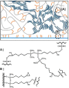
(A) Chemical structure of PEDOT:PSS. (B) Chemical structures of conjugated polymer/polyelectrolyte composites derived from PEDOT:PSS. (C) Frequently employed molecular additives to improve the performance, stability, or processability of PEDOT:polyelectrolyte-based composites.
Figure 11
Figure 11
Schematic highlighting the microstructure of PEDOT:PSS, including (a) the synthesis of short PEDOT segments (blue) onto the PSS template (gray), (b) the formation of colloidal particles in a dispersion, and (c) resulting PEDOT:PSS films with PEDOT:PSS-rich (blue) and PSS-rich (gray) phases. (d) Inset showing the formation of crystalline domains that benefit electronic charge carrier transport. Figure reproduced with permission from ref (50). Copyright 2016 Springer Nature under CC BY license https://creativecommons.org/licenses/by/4.0/.
Figure 12
Figure 12
(a) Electrical conductivity (blue trace) and K+ ion mobility (red trace) of PEDOT:PSS as a function of ethylene glycol formulation content. (b) Transconductance of the PEDOT:PSS-based OECT as a function of ethylene glycol formulation content. (c and d) Schematic highlighting the impact of ethylene glycol addition on the morphology of PEDOT:PSS and the associated changes in ionic and electronic charge carrier transport. The width of the red arrows denotes the relative ease of electronic and ionic charge carrier transport across the material. Figure adapted with permission from J. Rivnay et al. Copyright 2016 Springer Nature.
Figure 13
Figure 13
(a) Bending of PEDOT:PSS/[EMIM][TCM]-based OECTs. (b) Transfer curves of PEDOT:PSS/[EMIM][TCM]-based OECTs prior to and after bending. (c) Optical micrographs of PEDOT:PSS/[EMIM][TCM]-based films under various strains. Figure adapted with permission from ref (168). Copyright 2019 John Wiley and Sons.
Figure 14
Figure 14
Schematic highlighting the cross-linking mechanism of GOPS when blended with PEDOT:PSS onto a glass substrate. Figure adapted with permission from ref (172). Copyright 2017 John Wiley and Sons.
Figure 15
Figure 15
(A and B) Stabilities of Crys-P and EG-P in aqueous media over 21 days. (C and D) Stabilities of Crys-P and EG-P following autoclaving sterilization. (E) Operational stabilities of Crys-P and EG-P following 2000 electrochemical switching cycles. Figure adapted with permission from ref (178). Copyright 2018 Springer Nature.
Figure 16
Figure 16
(A) Chemical structures of PEDOT-S-based conjugated polyelectrolytes. (B) Chemical structures of PTHS-based conjugated polyelectrolytes. (C) Chemical structures of miscellaneous conjugated polyelectrolytes.
Figure 17
Figure 17
OECT performance and morphology of PTHS in the (A) absence and (B) presence of a 5% ethylene glycol additive. Figure adapted with permission from ref (190). Copyright 2014 John Wiley and Sons.
Figure 18
Figure 18
Small- and wide-angle X-ray scattering profiles recorded for PTHS-TMA+, PTHS-TMA+-co-P3HT 1, PTHS-TMA+-co-P3HT 2, PTHS-TMA+-co-P3HT 3, and P3HT. Figure adapted with permission from ref (220). Copyright 2019 American Chemical Society.
Figure 19
Figure 19
Different operating modes of electrolyte-gated OFETs employing P3CPT as channel material. Field-effect (regime I), interfacial electrochemical doping (regime II), and bulk electrochemical doping (regime III). Figure adapted with permission from A. Laiho et al. Copyright 2011 National Academy of Sciences.
Figure 20
Figure 20
Chemical structures of early conjugated polymers used for OECT applications.
Figure 21
Figure 21
Chemical structures of (A) gBDT, gBDT-T, gBDT-2T, gBDT-g2T, and g2T-T; (B) p(g2T2-T), g2T-T, p(g4T2-T), and p(g6T2-T); (C) gBDT-T2, gBDT-TT, and gBDT-MeOT2; (D) p(g2T-TT) and p(a2T-TT); (E) g-0%, g-50%, g-75%, g-100%, and 2g; (F) p(g3T2), p(g2T2-g4T2), p(g1T2-g5T2), and p(g0T2-g6T2); (G) P3MEEMT; (H) P3MEET, P3MEEMT, and P3MEEET; and (I) ProDOT(OE)-DMP.
Figure 22
Figure 22
MD simulations of g2T-T and p(g4T2-T) comparing their aggregation and solid-state ordering behavior. Figure adapted with permission from ref (268). Copyright 2020 American Chemical Society.
Figure 23
Figure 23
Capacitance and swelling recorded for the polymer series under the application of an applied voltage of +0.5 V versus the open-circuit potential (VOC). Figure adapted with permission from ref (274). Copyright 2020 John Wiley and Sons.
Figure 24
Figure 24
Electrochemical cycling stability recorded for p(g3T2), p(g2T2-g4T2), p(g1T2-g5T2), and p(g0T2-g6T2) over 2 h of continuous addressing. Figure adapted with permission from ref (277). Copyright 2020 John Wiley and Sons.
Figure 25
Figure 25
Chemical structures of (A) TFT-T; (B) p(gPyDPP-T2) and p(gPyDPP-MeOT2); (C) p(gDPP-TT), p(gDPP-T2), and p(gDPP-MeOT2); (D) PTDPP-DT; (E) PDPP[T]2{TEG}-EDOT and PDPP[T]2{TEG}-3-MEET; and (F) PIBET-O, PIBET-BO, and PIBET-AO.
Figure 26
Figure 26
Chemical structures of p(gNDI-gT2), p(C3-gNDI-gT2), and p(C6-gNDI-gT2).
Figure 27
Figure 27
Chemical structures of PgNgN and PgNaN.
Figure 28
Figure 28
Chemical structure of BBL.

References

    1. Rivnay J.; Owens R. M.; Malliaras G. G. The Rise of Organic Bioelectronics. Chem. Mater. 2014, 26, 679–685. 10.1021/cm4022003. - DOI
    1. Berggren M.; Richter-Dahlfors A. Organic Bioelectronics. Adv. Mater. 2007, 19, 3201–3213. 10.1002/adma.200700419. - DOI
    1. Simon D. T.; Gabrielsson E. O.; Tybrandt K.; Berggren M. Organic Bioelectronics: Bridging the Signaling Gap between Biology and Technology. Chem. Rev 2016, 116, 13009–13041. 10.1021/acs.chemrev.6b00146. - DOI - PubMed
    1. Someya T.; Bao Z.; Malliaras G. G. The Rise of Plastic Bioelectronics. Nature 2016, 540, 379–385. 10.1038/nature21004. - DOI - PubMed
    1. Paulsen B. D.; Tybrandt K.; Stavrinidou E.; Rivnay J. Organic Mixed Ionic-Electronic Conductors. Nat. Mater. 2020, 19, 13–26. 10.1038/s41563-019-0435-z. - DOI - PubMed

Publication types

LinkOut - more resources