

Assessing effects of exoskeleton misalignment on knee joint load during swing using an instrumented leg simulator
- PMID: 35090501
- PMCID: PMC8800279
- DOI: 10.1186/s12984-022-00990-z
Assessing effects of exoskeleton misalignment on knee joint load during swing using an instrumented leg simulator
Abstract
Background: Exoskeletons are working in parallel to the human body and can support human movement by exerting forces through cuffs or straps. They are prone to misalignments caused by simplified joint mechanics and incorrect fit or positioning. Those misalignments are a common safety concern as they can cause undesired interaction forces. However, the exact mechanisms and effects of misalignments on the joint load are not yet known. The aim of this study was therefore to investigate the influence of different directions and magnitudes of exoskeleton misalignment on the internal knee joint forces and torques of an artificial leg.
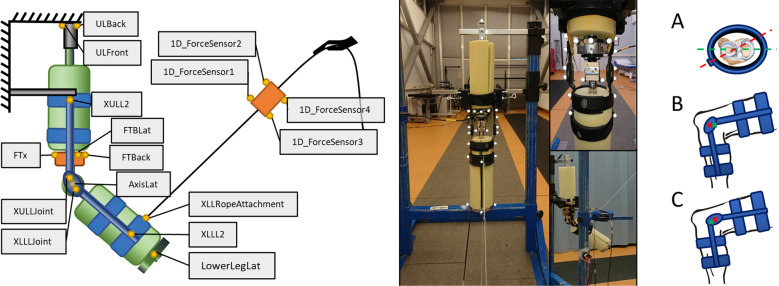
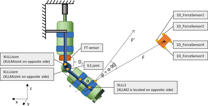
Methods: An instrumented leg simulator was used to quantify the changes in knee joint load during the swing phase caused by misalignments of a passive knee brace being manually flexed. This was achieved by an experimenter pulling on a rope attached to the distal end of the knee brace to create a flexion torque. The extension was not actuated but achieved through the weight of the instrumented leg simulator. The investigated types of misalignments are a rotation of the brace around the vertical axis and a translation in anteroposterior as well as proximal/distal direction.
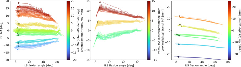
Results: The amount of misalignment had a significant effect on several directions of knee joint load in the instrumented leg simulator. In general, load on the knee joint increased with increasing misalignment. Specifically, stronger rotational misalignment led to higher forces in mediolateral direction in the knee joint as well as higher ab-/adduction, flexion and internal/external rotation torques. Stronger anteroposterior translational misalignment led to higher mediolateral knee forces as well as higher abduction and flexion/extension torques. Stronger proximal/distal translational misalignment led to higher posterior and tension/compression forces.
Conclusions: Misalignments of a lower leg exoskeleton can increase internal knee forces and torques during swing to a multiple of those experienced in a well-aligned situation. Despite only taking swing into account, this is supporting the need for carefully considering hazards associated with not only translational but also rotational misalignments during wearable robot development and use. Also, this warrants investigation of misalignment effects in stance, as a target of many exoskeleton applications.
Keywords: Exoskeletons; Joint load; Joint misalignments; Rehabilitation; Safety.
© 2022. The Author(s).
Conflict of interest statement
The authors declare that they have no competing interests.
Figures


References
-
- Shishehgar M, Kerr D, Blake J. A systematic review of research into how robotic technology can help older people. Smart Heal [Internet]. 2018;7–8:1–18.
-
- Bessler J, Prange-Lasonder G, Schaake L, Saenz J, Bidard C, Fassi I, et al. Safety assessment of rehabilitation robots: A review identifying safety skills and current knowledge gaps. Front Robot AI [Internet]. 2021;8:33. Available from: https://www.frontiersin.org/article/10.3389/frobt.2021.602878 - PMC - PubMed
-
- Rocon E, Ruiz AF, Raya R, Schiele A, Pons JL, Belda-Lois JM, et al. Human-robot physical interaction. Wearable robot biomechatronic exoskeletons [Internet] Chichester: John Wiley and Sons; 2008. pp. 127–163.
-
- Näf MB, Junius K, Rossini M, Rodriguez-Guerrero C, Vanderborght B, Lefeber D. Misalignment compensation for full human-exoskeleton kinematic compatibility: state of the art and evaluation. Appl Mech Rev [Internet]. 2018;70:1–19. doi: 10.1115/1.4042523/368929/Misalignment-Compensation-for-Full. - DOI
Publication types
MeSH terms
LinkOut - more resources
Full Text Sources
