Review
. 2022 Feb;32(1):6-22.
doi: 10.1016/j.zemedi.2021.11.003. Epub 2022 Jan 31.

The history of ion beam therapy in Germany

Affiliations
Review

The history of ion beam therapy in Germany

Oliver Jäkel et al. Z Med Phys. 2022 Feb.

Abstract

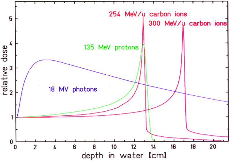
The advantageous depth dose profile of ion beams together with state of the art beam delivery and treatment planning systems allow for highly conformal tumor treatments in patients. First treatments date back to 1954 at the Lawrence Berkeley Laboratory (LBL) and in Europe, ion beam therapy started in the mid-1990s at the Paul-Scherrer Institute (PSI) with protons and at the Helmholtz Center for Heavy Ion Research (GSI) with carbon ions, followed by the Heidelberg Ion Therapy Center (HIT) in Heidelberg. This review describes the historical development of ion beam therapy in Germany based on the pioneering work at LBL and in the context of simultaneous developments in other countries as well as recent developments.

Keywords: Beam scanning; Carbon ion therapy; Light ion beam therapy; Relative biological effectiveness.


Figures

Figure 1
Figure 1
Comparison of the relative depth dose distributions of proton and carbon ions with18 MV photons as function of penetration depth. For the ion beams the energy deposition increases with penetration depth to the so-called Bragg maximum at the end of range. Changing the ion's energy, the position of the Bragg-maximum can be shifted in depth and the target volume can be covered with the high Bragg-peak dose (image reprinted from [2]).
Figure 2
Figure 2
Beam shaping of a pristine pencil beam (entering from the left) to an extended target volume (spread out Bragg peak, SOBP) by passive devices. The devices are schematically shown in the middle and their effects on the beam are shown above and below, respectively, for the lateral and longitudinal enlargement. Scattering by a multi-step device of heavy and light atomic material broadens the beam to a non-Gaussian shape with flat top. A range modulator is used to extend the Bragg peak longitudinally and produce the requested flat depth profile. With the range shifter the complete profile is shifted to the tumor depth. An adaption to the maximum contours of the tumor volume is achieved laterally by patient specific collimators and in depth by compensators. Using the passive technique, the resulting SOBP can only be tailored to the distal edge of the target volume at the expense of a corresponding high dose area in the proximal normal tissue (reprinted from [10]).
Figure 3
Figure 3
Absorbed dose distribution (black) for a depth modulated beam, leading to a constant RBE-weighted dose of 3 Gy in the target (red line). In this case, the RBE was calculated for cells with an α/β ratio of 2 Gy (Source: GSI).
Figure 4
Figure 4
Treatment positioning at LBL facility: The patient was fixed in front of the beam exit window at the left side. Also, the compensator, consisting of many individual PMMA rods is visible (Source: imaging archive of the Lawrence Berkeley National Laboratory, © 2010–2019 The Regents of the University of California, Lawrence Berkeley National Laboratory).
Figure 5
Figure 5
Treatment plan with five fixed horizontal fields showing a relatively large high-intermediate dose area in the normal tissue which limits the target dose (Source: imaging archive of the Lawrence Berkeley National Laboratory, © 2010–2019 The Regents of the University of California, Lawrence Berkeley National Laboratory).
Figure 6
Figure 6
Principles of the raster-scan system: the target volume is dissected into layers of equal particle ranges, which are covered by a net of individual beam positions. For each energy the beam is guided magnetically over the individual beam positions Reprinted from [25]). The raster scan technique at GSI was the first 3D application of carbon ions using an intensity controlled pencil beam scanning. But the idea of active beam scanning instead of passive beam application was virulent since 1980 when at NIRS used a 70 MeV proton beam to produce an irregular figure of 12 cm diameter with single beam spots of 1 cm in diameter. This experiment showed that a homogenous dose coverage of better 2% could be achieved. But this spot scanning technique was not extended to clinical relevant energies in 3D and was not used in clinical routine , similar to a scanning system proposed in Berkeley .
Figure 7
Figure 7
Left: Image of H. Helmholtz reproduced with 1.4 MeV/u C-ions at the micro-lithography facility at the GSI. Each spot corresponds to a single ion hit in a nuclear track detector. The low intensity beam was moved from one to the next pixel without turning of the beam. The image size was 0.3 mm × 0.5 mm (courtesy of B. Fischer, GSI Darmstadt). Right: Reproduction the famous photo of A. Einstein using a 430 MeV/u C-beam on a X-ray film of 15 cm × 18 cm. The beam of 1.7 mm FWHM in diameter contained 1.5 × 1010 ions in total and was moved using the raster-scan technology, developed on the basisof micro-beam technology (reprinted from [28]).
Figure 8
Figure 8
The dose distribution of a stopping carbon beam (dashed line) is compared to the β+ activity (red) induced by the carbon ions (reproduced from [57], [60]).
Figure 9
Figure 9
Layout of the Heidelberg Ion Beam Therapy facility (HIT) at the University Clinic Heidelberg. The facility is equipped with three ion sources (only 2 are shown here on the left side), a linac injector (left side), a synchrotron (upper left), two fixed horizontal treatment beams (central part) and an isocentric gantry (right side). The beam continues on the upper right side to an experimental area (not shown here), The facility offers beams of protons, carbon, helium and oxygen ions and uses beam scanning delivery only (Image: Heidelberg University Clinic).

References

    1. Wilson R.R. Radiological use of fast protons. Radiology. 1946;47(5):487–491. - PubMed
    1. Bethge K., Kreisler K.G.P., Walter G. Springer; Heidelberg: 2004. Hadron therapy in medical applications of nuclear physics.
    1. Tobias C., et al. Pituitary irradiation with high-energy proton beams a preliminary report. Cancer Res. 1958;18(2):121–134. - PubMed
    1. Linstadt D.E., Castro J.R., Phillips T.L. Neon ion radiotherapy: results of the phase I/II clinical trial. Int J Radiat Oncol Biol Phys. 1991;20(4):761–769. - PubMed
    1. Larsson B. Pre-therapeutic physical experiments with high energy protons. Br J Radiol. 1961;34(399):143–151. - PubMed

LinkOut - more resources