Review
. 2022 Feb 10;14(6):2091-2118.
doi: 10.1039/d1nr06303k.

Magnetogenetics: remote activation of cellular functions triggered by magnetic switches

Affiliations
Review

Magnetogenetics: remote activation of cellular functions triggered by magnetic switches

Susel Del Sol-Fernández et al. Nanoscale. .

Abstract

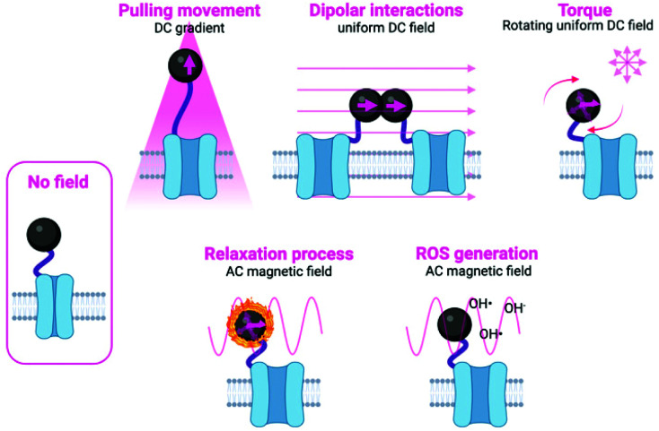
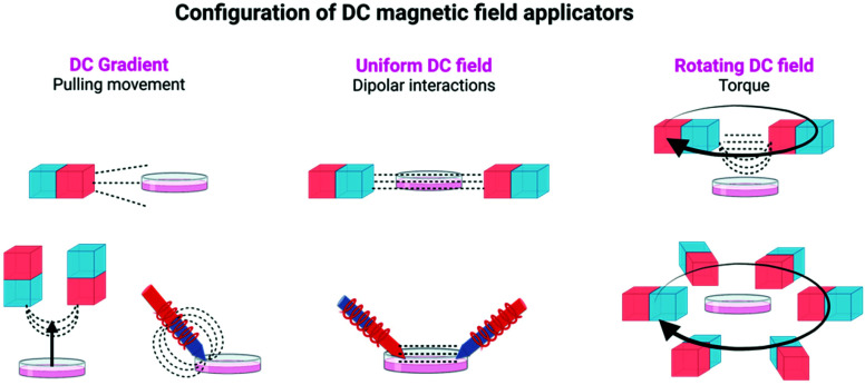
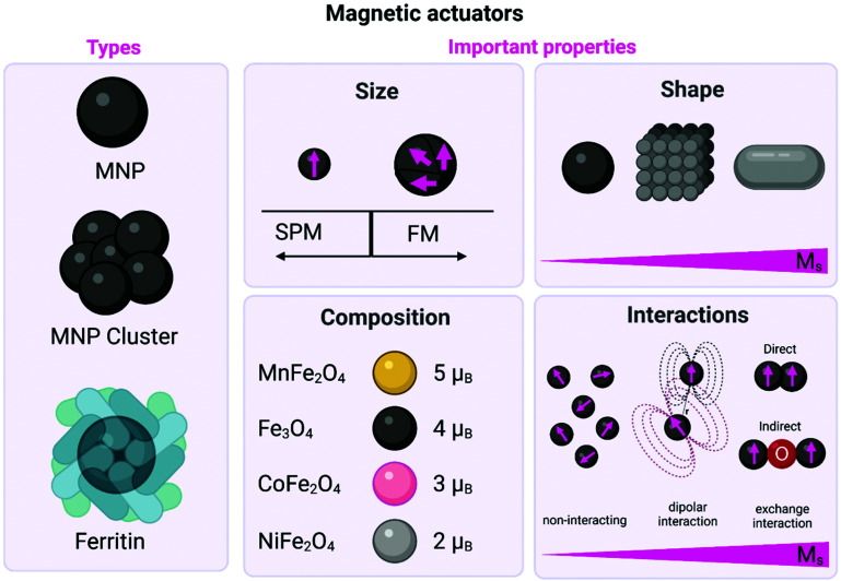
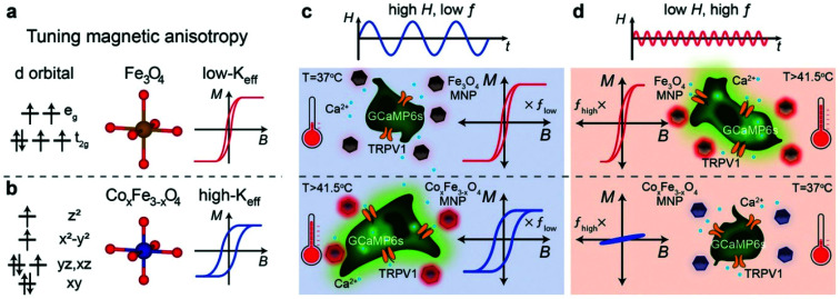
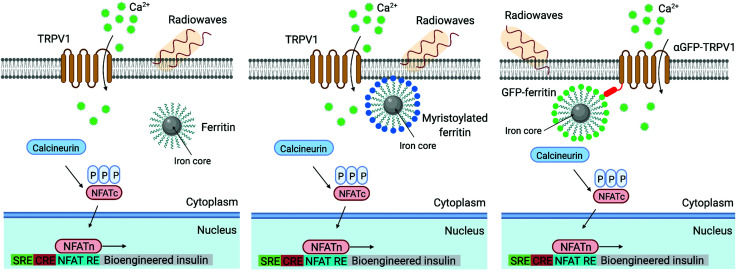
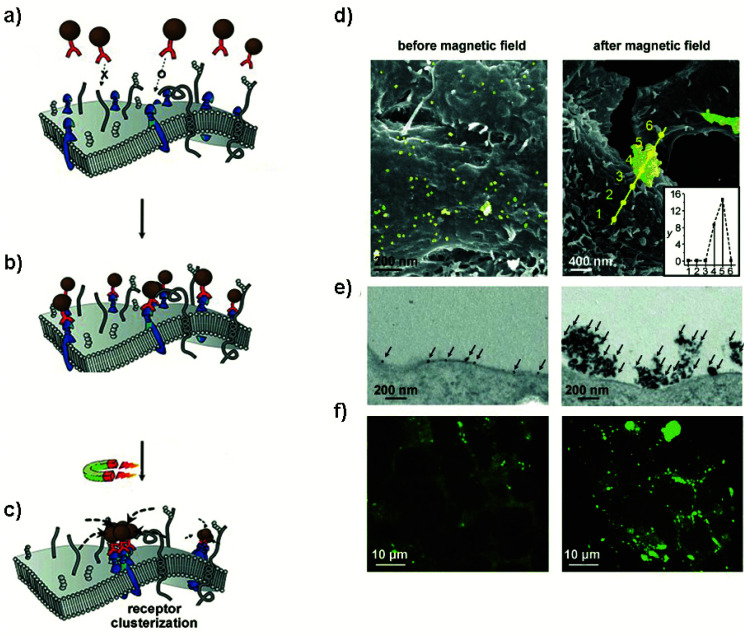
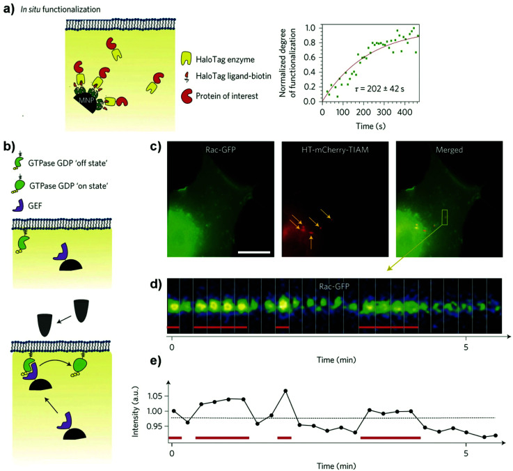
During the last decade, the possibility to remotely control intracellular pathways using physical tools has opened the way to novel and exciting applications, both in basic research and clinical applications. Indeed, the use of physical and non-invasive stimuli such as light, electricity or magnetic fields offers the possibility of manipulating biological processes with spatial and temporal resolution in a remote fashion. The use of magnetic fields is especially appealing for in vivo applications because they can penetrate deep into tissues, as opposed to light. In combination with magnetic actuators they are emerging as a new instrument to precisely manipulate biological functions. This approach, coined as magnetogenetics, provides an exclusive tool to study how cells transform mechanical stimuli into biochemical signalling and offers the possibility of activating intracellular pathways connected to temperature-sensitive proteins. In this review we provide a critical overview of the recent developments in the field of magnetogenetics. We discuss general topics regarding the three main components for magnetic field-based actuation: the magnetic fields, the magnetic actuators and the cellular targets. We first introduce the main approaches in which the magnetic field can be used to manipulate the magnetic actuators, together with the most commonly used magnetic field configurations and the physicochemical parameters that can critically influence the magnetic properties of the actuators. Thereafter, we discuss relevant examples of magneto-mechanical and magneto-thermal stimulation, used to control stem cell fate, to activate neuronal functions, or to stimulate apoptotic pathways, among others. Finally, although magnetogenetics has raised high expectations from the research community, to date there are still many obstacles to be overcome in order for it to become a real alternative to optogenetics for instance. We discuss some controversial aspects related to the insufficient elucidation of the mechanisms of action of some magnetogenetics constructs and approaches, providing our opinion on important challenges in the field and possible directions for the upcoming years.


Conflict of interest statement

There are no conflicts to declare.

Figures

Fig. 1
Fig. 1. Schematic representation of the different mechanisms used to manipulate magnetic actuators, classified indicating the type of magnetic field (either DC or AC) and the type of activation being used. Figure created with BioRender.com.
Fig. 2
Fig. 2. Different configurations of DC magnetic field applicators commonly used in magnetogenetic experiments, using either permanent magnets or electromagnets. Figure created with BioRender.com.
Fig. 3
Fig. 3. Schematic representation of the different types of magnetic actuators including both MNPs (either single core or clusters) and ferritin. The main physicochemical properties that affect their magnetic behaviour are also described including: (i) the influence of the size on the domain structure and the onset of superparamagnetism (SPM) and/or ferrimagnetism (FM) state; (ii) the impact of the shape on the Ms values; (iii) the impact of the composition on the magnetic moment per unit cell in the ferrite structure; and (iv) the impact of the interactions on the Ms values. Figure created with BioRender.com.
Fig. 4
Fig. 4. (a and b) Schematic illustration showing the concept of selective magnetothermal stimulation of cells using MNPs with different magnetic anisotropy. (c and d) Response of each type of MNP to different AMF conditions and subsequent effect on TRPV1 thermal activation. Reprinted with permission from J. Moon, et al., Adv. Funct. Mater., 2020, 30, 2000577. “Magnetothermal Multiplexing for Selective Remote Control of Cell Signaling”, copyright (2020) WILEY-VCH Verlag GmbH & Co. KGaA, Weinheim.
Fig. 5
Fig. 5. Examples of diverse membrane receptor signalling pathways that can be manipulated using magnetic actuators, including integrins, E-cadherin, TRPV4 and Frizzled. The physiological mechanisms of activation of these receptors are shown in green. See text for further details. Figure created with BioRender.com.
Fig. 6
Fig. 6. (A) 250 nm carboxy-dextran MNPs covalently functionalised with UM206 peptide by carbodiimide chemistry. (B) Human mesenchymal stem cells labelled with UM206-MNPs; the labelled cells were stimulated with oscillating magnetic fields or injected into foetal chick femurs before magnetic field stimulation. (C) Alternating magnetic fields were applied to samples using a magnetic bioreactor system (MICA Biosystems) consisting of arrays of permanent magnets situated beneath the samples. Adapted from Nanomedicine: Nanotechnology, Biology and Medicine, M. Rotherham, et al., “Remote regulation of magnetic particle targeted Wnt signalling for bone tissue engineering”. vol. 14, pp. 173–184, copyright (2018), with permission from Elsevier. Figure adapted with BioRender.com.
Fig. 7
Fig. 7. Magnetogenetic activation of HEK-293 cells and control of behavioural responses in C. elegans by remote magnetic stimulation. (a) Schematic of magnetic stimulation of MAR co-transfected HEK-293 cells together with the calcium indicator GCaMP6s with a pair of electrical coils. (b) Change of fluorescence intensity before and after remote magnetic stimulation. (c) Epifluorescence (left) and bright field (right) images of transgenic C. elegans expressing MAR under the promoter myo-3. (d) Body contraction before (top) and after magnetic field application (bottom). (e) Measurements of body length before and after magnetic field application at different time points. While C. elegans expressing MAR under myo-3 promoter showed body contraction (orange trace), N2 wild type showed no obvious change of body length after magnetic stimulation. Reprinted from Long, X. et al., Magnetogenetics: Remote Non-Invasive Magnetic Activation of Neuronal Activity with a Magnetoreceptor. Sci. Bull., 2015, 60(24), 2107–2119 (article distributed under the terms of the Creative Commons CC-BY license).
Fig. 8
Fig. 8. Scheme of magnetic technique and modulation of excitatory N-type Ca2+ channels in an FXS neural network model following magnetic stimulation. (a) Schematic of the technique. Neurons grown on substrates that produce high local field gradients are stimulated with MNPs and a permanent magnet to induce calcium influx. (b) Fluorescence microscopy images showing an increase in calcium both in (i) the cell body and (ii) the axonal boutons. (c) FXS model neurons (FMRP) express more N-type calcium ion channels than normal neurons. With age, however, there is a decrease in N-type calcium ion channel expression. Immunostaining of N-type calcium ion channels in the FXS model neurons (top) and control neurons (bottom). (d) FXS model neurons and (e) FXS model neurons after magnetic chronic stimulation. A decrease in N-type calcium ion channel florescent intensity is observed in (e). Reprinted with permission from Tay, A., & Di Carlo, D. (2017). Magnetic Nanoparticle-Based Mechanical Stimulation for Restoration of Mechano-Sensitive Ion Channel Equilibrium in Neural Networks. Nano letters, 17(2), 886–892. Copyright (2017) American Chemical Society.
Fig. 9
Fig. 9. Magnetomechanical stimulation of MND-decorated DRG neurons allows for remote activation of Ca2+ influx. (a–c) Schematic representation of the three possible configurations of magnetic spins in MNDs: (a) vortex, (b) in-plane, and (c) out-of-plane (see section 2.2.1. for further details). (d) DRGs relay mechanosensory information to the spinal cord. DRG explants were incubated with MNDs and stimulated using slowly varying (≤5 Hz) magnetic fields. MNDs were then magnetized in a direction compatible with their easy axes (on the plane of the disk), generating force on ion channels and the concomitant mechanical torque and Ca2+ influx. (e) SEM image of the DRG explant culture surface incubated with individual MNDs that can be observed on the surface. Scale bar = 2 μm. (f) Comparison of the efficacy (percentage of stimulated cells in calcium imaging) of magnetomechanical stimulation for 226 and 98 nm diameter MNDs on DRGs or hippocampal neurons (Hipp). A two-way ANOVA was conducted on the influence of culture (DRG or Hipp) and MND type (226, 98 nm or none), being significant the main effects for culture type and the interaction. Reprinted with permission from Gregurec, D., et al., “Magnetic Vortex Nanodiscs Enable Remote Magnetomechanical Neural Stimulation”. ACS Nano, 2020, 14(7), 8036–8045. Copyright (2020) American Chemical Society.
Fig. 10
Fig. 10. Magnetomechanical gating of Piezo1 ion channel in cultured neurons with m-Torquer system. (a) Schematic of the nanoscale m-Torquer system. The m-Torquer system is composed of a rotating uniform magnetic field (∇B ≈ 0) generated by a circular magnet array (CMA) and a nanoparticle m-Torquer generator. The working distance of the m-Torquer system can be increased to tens of centimetres with the potential application. (b) TEM image of 25 nm octahedral MNPs. Scale bar, 50 nm. (c) TEM tilting analysis shows the octahedral shape of nanoparticles. Scale bars, 20 nm. (d) High-resolution TEM image of the MNPs. Scale bar, 2 nm. (e) SEM images of m-Torquers composed of assembled monolayer octahedral nanoparticles on a spherical support via click chemistry. Scale bar, 200 nm and 100 nm. (f) Schematic of genetic encoding of Piezo1 by Ad-Piezo1 with human cytomegalovirus (CMV) promotor and its magnetomechanical gating with specifically targeted m-Torquer with Myc antibody. Reprinted by permission from Springer Nature, Nature Materials, “Non-Contact Long-Range Magnetic Stimulation of Mechanosensitive Ion Channels in Freely Moving Animals”, Jung-uk Lee et al., Copyright (2021).
Fig. 11
Fig. 11. (a) Principle of TRPV1 opening post-thermal stimulation with MNPs and AC fields. Streptavidin-DyLight549-coated MNPs bind to the biotinylated membrane protein AP-CFP-TM. (b) Variation of the local temperature at the plasma membrane (red) and the Golgi apparatus (green), measured by the changes in the fluorescence intensity of DyLight549 (membrane) and Golgi-targeted GFP (Golgi apparatus), respectively. (c) Fluorescence image sequence of the head region of a C. elegans worm labelled with MNPs. The white squares indicate the retraction movement of the animals as a consequence of the increase in temperature upon the application of the AC field (thermal avoidance). (d) Time-dependence of the fluorescence intensity and temperature of the amphid region of the worm. (e) Bright-field image of the worm, indicating the head region labelled with MNPs. (f) Schematic drawing of the head region and its structures. Reprinted by permission from Springer Nature, Nature Nanotechnology, “Remote control of ion channels and neurons through magnetic-field heating of nanoparticles”, H. Huang, S. Delikanli, H. Zeng, D. M. Ferkey, A. Pralle, copyright (2010).
Fig. 12
Fig. 12. (a) Principle of the magnetothermal activation approach using AITC bound to MNP surface through a thermolabile linker, which can be cleaved upon exposure to the AMF. (b) 3D scheme of the experimental setup, depicting the AMF coil and the sample chamber. (c) Plot of the field amplitude as a function of the position (finite element simulation of the coil cross section). (d) and (e) Fluorescence images of neurons expressing TRPV1 and GCaMP6s and treated with AITC-modified MNPs before (d) and after 15 s of exposure to the AMF (e). The increase in the fluorescence intensity observed in (e) indicates Ca2+ influx. Reprinted with permission from G. Romero, et al., Adv. Funct. Mater., 26, 6471–6478, “Localized Excitation of Neural Activity via Rapid Magnetothermal Drug Release”, copyright (2016), WILEY-VCH Verlag GmbH & Co. KGaA, Weinheim.
Fig. 13
Fig. 13. (a) Left: Magnetothermal activation of thermosensitive TRPV1 ion channels with MNPs bound to the cell membrane. Right: experimental setup for in vitro experiments, combining the AMF application with fluorescence microscopy. (b) Experimental setup for in vivo magnetothermal stimulation of motion behaviour of awake mice and photograph of the animal in the observation zone (depicted as arena). (c) 1 min-long trajectories of a mouse stimulated in the motor cortex before (black), during (red), and after (blue) field application, showing a fast movement around the arena. (d) 1 min-long trajectories of a mouse stimulated in the caudate putamen nuclei. In this case, the animal remained near the centre of the arena and rotated around its body axis. (e) 1 min-long trajectories of a mouse stimulated near the ridge between dorsal and ventral striatum, showing the freezing of gait. The “frozen” position of the mouse paws is shown in the right bottom photograph. Reprinted from R. Munshi, et al., “Magnetothermal genetic deep brain stimulation of motor behaviors in awake, freely moving mice”, eLife, 2017, 6, e27069, copyright 2017, (article distributed under the terms of Creative Commons Attribution 4.0 International License).
Fig. 14
Fig. 14. Schematic depiction of three alternate locations of genetically encoded ferritin nanoparticles used to trigger the TRPV1 opening: cytoplasmic (left), membrane-tethered (middle) and channel-associated (right). Adapted by permission from Springer Nature, Nature Medicine, “Remote regulation of glucose homeostasis in mice using genetically encoded nanoparticles”, S. A. Stanley, J. Sauer, R. S. Kane, J. S. Dordick, J. M. Friedman, copyright (2015). Figure created with BioRender.com.
Fig. 15
Fig. 15. Clustering of Tie2 receptors using MNPs. (a–c) Targeting and magnetic manipulation of Ab-Zn-MNPs. (a and b) MNPs modified with a monoclonal antibody against Tie2 receptors, selectively bind to them. (c) After applying an external magnetic field, the Ab-Zn-MNPs form aggregates, inducing the clustering of Tie2 receptors. (d–f) Magnetism-induced aggregation of Ab-Zn-MNPs on the cell surface. (d) SEM images of the MNPs on the cell surface before and after magnetic field application. Ab-Zn-MNPs are shown in yellow for clear visibility. MNP aggregates after applying the magnetic field were analysed using EDX. A high Fe content was found on the aggregates (inset in the image on the right). (e) TEM images of the MNPs (indicated by arrows) before and after magnetic field application. (f) Fluorescence confocal microscopy images of MNPs before and after application of a magnetic field. Reproduced with permission from Lee, J.-H. et al., Angewandte Chemie International Edition, 49, 5698–5702 (2010), “Artificial Control of Cell Signaling and Growth by Magnetic Nanoparticles” copyright (2010) Wiley-VCH Verlag GmbH & Co. KGaA.
Fig. 16
Fig. 16. In vivo magnetic apoptosis signalling for zebrafish. (a) Scheme of the magnetogenetic experiment in zebrafish. Ab–MNPs functionalized with fluorescein are injected into yolk of embryo at one-cell stage to label OTR. At 24 h post-fertilization (h. p. f.), zebrafish are divided into two groups (control and activated with magnetic field). (b) Bright-field microscope images of three groups of animals, (i) control, (ii) incubated with Ab-MNPs and non-activated and (iii) incubated with Ab-MNPs and magnetically activated. The latter group shows morphological alterations in the tail region when compared with other groups. (c) Quantitative analysis on morphological alterations (tail bending) after applying magnetic hyperthermia. The angle between the line on the pronephros (PR) and the line of tail tip (TT) is measured for each group. (d–f) Fluorescence images of zebrafish showing the activation of caspase-3 after magnetic manipulation: Ab–MNPs is shown in green, whereas active caspase-3 is shown in red. Red fluorescence is only observed in the tail region of group iii, treated with MNPs and stimulated with the magnetic field. (f) Magnified images of active caspase-3. (g) Graph quantifying the number of cells positive for caspase-3 activity (***P < 0.001). Reprinted by permission from Springer Nature, Nature Materials, “A magnetic switch for the control of cell death signalling in in vitro and in vivo systems”, Mi Hyeon Cho et al., copyright (2012).
Fig. 17
Fig. 17. (a) In situ functionalization scheme: Left: streptavidin-coated MNPs functionalized with a biotinylated -HaloTag Ligand (HTL) are microinjected into cells expressing the protein of interest fused to the HaloTag. The HaloTag binds irreversibly to its ligand, recruiting the protein of interest to the MNP. Right: kinetics of HaloTag–mCherry binding to HTL-MNPs. (b) Remote control of Rho-GTPase signalling at the plasma membrane: Top: GEF-MNP is in the cytoplasm. Bottom: magnetic forces attract the GEF-MNP to the membrane, where it can catalyse GTPase activation. (c) COS7 cell co-expressing Rac1-GFP (green) and HaloTag–mCherry–TIAM1 (red). TIAM-MNPs appear as bright red spots and are highlighted by arrows. (d) Kymograph showing Rac1-GFP recruitment on top of a TIAM-MNP over time. Red bars indicate the presence of the magnetic tip. (e) Quantification of the Rac1-GFP recruitment at the TIAM-MNP surface. Reprinted by permission from Springer Nature, Nature Nanotechnology, “Subcellular control of Rac-GTPase signalling by magnetogenetic manipulation inside living cells”, Etoc, F.; Lisse, D.; Bellaiche, Y.; Piehler, J.; Coppey, M.; Dahan, M., copyright (2013).
None
From left to right: Lucía Gutiérrez, Raluca Fratila, Pilar Gomollón, Pablo Martínez, Christian Castro, Susel del Sol and María Moros.

References

    1. Jaalouk D. E. Lammerding J. Nat. Rev. Mol. Cell Biol. 2009;10:63–73. doi: 10.1038/nrm2597. - DOI - PMC - PubMed
    1. Repina N. A. Rosenbloom A. Mukherjee A. Schaffer D. V. Kane R. S. Annu. Rev. Chem. Biomol. Eng. 2017;8:13–39. doi: 10.1146/annurev-chembioeng-060816-101254. - DOI - PMC - PubMed
    1. Stanley S. A. Friedman J. M. Cold Spring Harb. Perspect. Med. 2019;9:a034322. doi: 10.1101/cshperspect.a034322. - DOI - PMC - PubMed
    1. Monzel C. Vicario C. Piehler J. Coppey M. Dahan M. Chem. Sci. 2017;8:7330–7338. doi: 10.1039/C7SC01462G. - DOI - PMC - PubMed
    1. Connell J. J. Patrick P. S. Yu Y. Lythgoe M. F. Kalber T. L. Regen. Med. 2015;10:757–772. doi: 10.2217/rme.15.36. - DOI - PubMed