. 2022 Jan 26;8(1):67-76.
doi: 10.1021/acscentsci.1c01234. Epub 2021 Dec 20.

Visible Light Chemical Micropatterning Using a Digital Light Processing Fluorescence Microscope

Affiliations

Visible Light Chemical Micropatterning Using a Digital Light Processing Fluorescence Microscope

Uroob Haris et al. ACS Cent Sci. .

Abstract

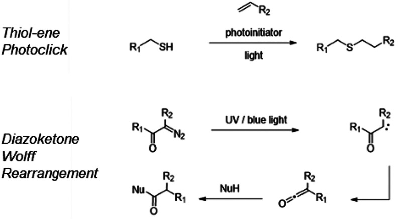
Patterning chemical reactivity with a high spatiotemporal resolution and chemical versatility is critically important for advancing revolutionary emergent technologies, including nanorobotics, bioprinting, and photopharmacology. Current methods are complex and costly, necessitating novel techniques that are easy to use and compatible with a wide range of chemical functionalities. This study reports the development of a digital light processing (DLP) fluorescence microscope that enables the structuring of visible light (465-625 nm) for high-resolution photochemical patterning and simultaneous fluorescence imaging of patterned samples. A range of visible-light-driven photochemical systems, including thiol-ene photoclick reactions, Wolff rearrangements of diazoketones, and photopolymerizations, are shown to be compatible with this system. Patterning the chemical functionality onto microscopic polymer beads and films is accomplished with photographic quality and resolutions as high as 2.1 μm for Wolff rearrangement chemistry and 5 μm for thiol-ene chemistry. Photoactivation of molecules in living cells is demonstrated with single-cell resolution, and microscale 3D printing is achieved using a polymer resin with a 20 μm xy-resolution and a 100 μm z-resolution. Altogether, this work debuts a powerful and easy-to-use platform that will facilitate next-generation nanorobotic, 3D printing, and metamaterial technologies.


Conflict of interest statement

The authors declare the following competing financial interest(s): A.R.L. discloses a financial stake in BioLum Sciences, LLC.

Figures

Figure 1
Figure 1
(A) Design scheme and (B) photograph of the DLP microscope setup composed of (1) a DLP LightCrafter 4500 as the patterned light source; (2) a light collimation assembly consisting of an adjustable iris diaphragm and an achromatic doublet collimation lens with a 100 mm focal length mounted in a zoom housing with 4.1 mm linear travel; (3) an xy-translational stage and slide holder; (4) a 4× objective (NA = 0.10), a 40× objective (NA = 0.60), or a 100× oil objective (NA = 1.30) mounted in a zoom housing with 4.1 mm linear travel; (5) a fluorescence imaging filter cube containing a 650 nm short-pass excitation filter, a 660 nm dichroic beamsplitter, and a 692/40 nm bandpass emission filter; (6) a mounted 100 mm focal length achromatic doublet lens in a 2.5” lens tube and a 1.0” spacer; and (7) a Chameleon3Monochrome sCMOS camera. Part details are provided in Table S1. (C) Checkerboard pattern and one-pixel-width diagonal lines projected onto a target resolution slide using 4×, 40×, and 100× objectives. The projection resolution with each objective was determined as the fwhm of the Gaussian fit (black line) to imaged pixel intensities (blue circles) across projected one-pixel-wide lines. The error on the fwhm is ±SD with n = 3 different lines measured.
Scheme 1
Scheme 1. Light-Based Thiol–Ene Photoclicking and Wolff Rearrangement of Diazoketones
Figure 2
Figure 2
Visible-light-mediated reaction systems for solid microprinting. (A) Synthesis of the thiol-functionalized SH–resin. (B) Synthesis of the fluorophore-tagged alkene, SiR–sty. (C) Reaction scheme and EVOS-fl fluorescence images (Ex = 635/18 nm and Em= 692/40 nm) of washed SH–resin beads after being reacted in a solution of 3 mM SiR–sty and 70 μM eosin y in DMSO for 22 h with and without blue light irradiation from a 100 W LED lamp at 0.04 W cm–2. (D) Reaction scheme and EVOS-fl fluorescence images (Ex = 542/20 nm and Em = 593/40 nm) of PVA films doped with 20 μM RhBNN with and without 22 h blue light irradiation from a 100 W LED lamp at 0.04 W cm–2. The insets show brightfield images.
Figure 3
Figure 3
DLP micropatterning characterization. For DLP micropatterning with a 4× objective: fluorescence DLP microscope image of the SH–resin in SiR–sty (A) during irradiation with 0.5 W cm–2 blue light in a grid pattern for 15 min using a 4× objective and (B) after irradiation, imaged under uniform excitation through a 692/40 nm emission filter. (C) EVOS-fl microscope image of the resin from panel B after washing with DMSO (Ex = 635/18 nm and Em = 692/40 nm). DLP fluorescence images of the 20 μM RhBNN–PVA film (D) during irradiation with 0.5 W cm–2 blue light in a grid pattern for 10 min through a 4× objective and (E) after irradiation, imaged under uniform green light excitation through a 692/40 nm emission filter. (F) EVOS-fl fluorescence image of the PVA film from panel E (Ex = 542/20 nm and Em = 593/40 nm). For DLP micropatterning using a 40× objective: (G) on-resin thiol–ene patterning contrast between light and dark areas of horizontal-line-patterned beads with increasing blue light irradiation time at 17.9 W cm–2. (H) RhBNN–PVA film patterning contrast with increasing blue light irradiation time at 17.9 W cm–2. (I) Patterning contrast with varying LED colors for thiol–ene bead micropatterning after 10 min of irradiation with 8.5 W cm–2 blue, green, or red light. (J) Patterning contrast with varying LED colors for RhBNN–PVA film micropatterning after 2 min of irradiation with 8.5 W cm–2 blue, green, or red light. (K) Patterning resolution determination. DLP fluorescence images and representative Gaussian fits (black line) to the pixel intensity data (blue circles) for on-resin thiol–ene and in-film rhodamine B uncaging in a horizontal line or grid pattern using 4×, 40×, and 100× objectives. Errors for panels G–K are ±SE with n = 9–19 different patterned lines across 3–6 independent replicates. Images B, C, F, and K (4× objective on-bead and 40× and 100× objective in-film) are brightness- and contrast-enhanced; raw images are available in the Supporting Information.
Figure 4
Figure 4
DLP micropatterning of live A549 cells using visible light. DLP fluorescence image of cells incubated for 30 min with 20 μM RhBNN under a 40× objective (A) before blue light irradiation and (B) after 30 s of blue light irradiation at 9.4 W cm–2 with a split field pattern, which irradiates the left half of the field. (C) Plot of average pixel intensities of all cells in the irradiated (left of the dotted line in panel B) or nonirradiated (right of the dotted line in panel B) half of the field with increasing irradiation times. Error bars are ±SD with n = 3 independent replicates. Images A and B are equally brightness- and contrast-enhanced; raw images available in the Supporting Information.
Figure 5
Figure 5
Optimization of DLP microscale photocuring and print resolution determination. (A) Plot of the cured print width against the irradiation time at green light irradiation intensities of 48, 83, and 160 mW cm–2. The projected pattern width was 74 μm (dotted line). (B) Light microscopy images of washed prints formed on glass slides after photocuring using 83 mW cm–2 blue (H-Nu 470 initiator), green (Rose Bengal initiator), or red (ZnTPP initiator) irradiation light for 2 s in a checkerboard pattern. (C) Plot of the cured print width against the irradiation time at irradiation intensities of 48, 83, and 160 mW cm–2. The projected pattern width was 21 μm. The dotted line represents the highest average print resolution achieved. (D) Photograph of 3D printed pyramids printed using the DLP microscope and blue-light-initiated polymer resin. Patterned light at 140 mW cm–2 was projected for 2 s per layer onto the bottom of a fluorinated film-lined beaker containing liquid resin, and prints were built onto a glass print bed affixed to a motorized stage for z-translation.
Figure 6
Figure 6
Demonstration of DLP microscale photocuring, 3D printing, on-bead micropatterning, live-cell labeling, and film patterning. Fluorescence DLP images of microscale photocured solid resin showing (A) a maze pattern; (B) a microfluidics pattern; (C) a printed circuit board pattern; (D) the SMU mustang mascot; (E) neuron, mitochondria, and DNA clipart; and (F) alphabet text. (G) Fluorescence images of a DLP 3D microprinted rook and pyramids. Thiol–ene patterning of SiR-Sty on SH–resin beads in (H) a grid pattern, (I) a yin-yang pattern, (J) alphabet text, and (K) the SMU mustang mascot and “PONY UP” slogan. Rhodamine B modification of NH2-resin beads in (L) a checkerboard pattern and (M) a star pattern. (N) Dual patterning of RhBNN (fluorescence imaged through a 593/20 nm filter) and SiR–sty (fluorescence imaged through a 692/40 nm filter) on SH–resin beads in (i) a checkerboard and horizontal line pattern and (ii) a pattern of vertical and horizontal lines. Fluorescence images of live A549 cells labeled with rhodamine B in (O) a split field pattern, (P) a checkerboard pattern, and (O) a desired single cell labeled in a confluent field of cells. Fluorescence DLP images of microprinting in RhBNN–PVA films showing (R) the Dallas Hall building, (S) the DLP microscope, (T) a pet cat, (U) a QR code, (V) a printed circuit board pattern, (W) the United States Air Force resolution test pattern, (X) rocket and airplane clipart, (Y) “I heart Science” text, and (Z) the structure of rhodamine BNN. Scale bars correspond to the magnifying objective used for patterning and imaging; the scale bar represents 500 μm with a 4× objective, 50 μm with a 40× objective, and 20 μm with 100× objective. Images I, J, N–R, and T– W are brightness- and contrast-enhanced; raw images are available in the SI.

References

    1. Liddle J. A.; Gallatin G. M. Nanomanufacturing: A Perspective. ACS Nano 2016, 10 (3), 2995–3014. 10.1021/acsnano.5b03299. - DOI - PMC - PubMed
    1. Li J.; Pumera M. 3D printing of functional microrobots. Chem. Soc. Rev. 2021, 50 (4), 2794–2838. 10.1039/D0CS01062F. - DOI - PubMed
    1. Lee M.; Rizzo R.; Surman F.; Zenobi-Wong M. Guiding Lights: Tissue Bioprinting Using Photoactivated Materials. Chem. Rev. 2020, 120 (19), 10950–11027. 10.1021/acs.chemrev.0c00077. - DOI - PubMed
    1. Wang L.; Pumera M. Recent advances of 3D printing in analytical chemistry: Focus on microfluidic, separation, and extraction devices. TrAC, Trends Anal. Chem. 2021, 135, 116151.10.1016/j.trac.2020.116151. - DOI
    1. Hüll K.; Morstein J.; Trauner D. In Vivo Photopharmacology. Chem. Rev. 2018, 118 (21), 10710–10747. 10.1021/acs.chemrev.8b00037. - DOI - PubMed

LinkOut - more resources