. 2022 Feb 17;126(6):1242-1253.
doi: 10.1021/acs.jpcb.1c09441. Epub 2022 Feb 8.

Structural Forces in Ionic Liquids: The Role of Ionic Size Asymmetry

Affiliations

Structural Forces in Ionic Liquids: The Role of Ionic Size Asymmetry

J Pedro de Souza et al. J Phys Chem B. .

Abstract

Ionic liquids (ILs) are charged fluids composed of anions and cations of different size and shape. The ordering of charge and density in ILs confined between charged interfaces underlies numerous applications of IL electrolytes. Here, we analyze the screening behavior and the resulting structural forces of a representative IL confined between two charge-varied plates. Using both molecular dynamics simulations and a continuum theory, we contrast the screening features of a more-realistic asymmetric system and a less-realistic symmetric one. The ionic size asymmetry plays a nontrivial role in charge screening, affecting both the ionic density profiles and the disjoining pressure distance dependence. Ionic systems with size asymmetry are stronger coupled systems, and this manifests itself both in their response to the electrode polarization and spontaneous structure formation at the interface. Analytical expressions for decay lengths of the disjoining pressure are obtained in agreement with the pressure profiles computed from molecular dynamics simulations.


Conflict of interest statement

The authors declare no competing financial interest.

Figures
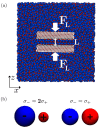
Figure 1
Figure 1
MD simulations. (a) Snapshot of the asymmetric IL immersing two charged surfaces in a fully periodic simulations box. The surfaces are pushed together along the z-direction with a normal force FL to ultimately calculate the pressure as a function of the separation distance, L. (b) The ionic sizes, characterized by the LJ diameter, σi, for the (left) asymmetric and (right) symmetric systems.
Figure 2
Figure 2
Charge and ion density profiles in asymmetric ILs between the charged plates. Rows correspond to the fixed surface charge densities of (a,b) qs = 0.12 C/m2, (c,d) qs = 0 C/m2, and (e,f) qs = −0.12 C/m2. Columns correspond to the squeeze out of a central electroneutral layer between two stable states where (a,c,e) L ≈ 2.2 nm and (b,d,f) L ≈ 1.5 nm. Cumulative charge functions are plotted to the left or right of the corresponding concentration profile plot. Markers (○) simulations; lines (—) theory. Color coding: blue, anions; red, cations.
Figure 3
Figure 3
Charge and ion density profiles in symmetric IL. Rows correspond to the fixed surface charge of (a,b) qs = 0 C/m2, (c,d) qs = −0.06 C/m2, and (e,f) qs = −0.12 C/m2. Columns correspond to the squeeze out of a central electroneutral layer between two stable states where (a,c,e) L ≈ 2 nm and (b,d,f) L ≈ 1.4 nm. Cumulative charge functions are plotted to the left or right of the corresponding concentration profile plot. Markers (○) simulations; lines (—) theory. Color coding: blue, anions; red, cations.
Figure 4
Figure 4
Disjoining pressure profiles. (a–c) Asymmetric system and (d–f) symmetric system for (a,d) negative, (b,e) uncharged, and (c,f) positive surfaces. The black markers (○) are the MD simulation data points. The solid orange lines are the full, nonlinear integro-differential theory. The other dashed and dash-dot lines are applications of the approximation in eq 14, where the parameters P0 and z0 are fit only to the first minimum. Here, the cyan dash-dot lines correspond to the analytical expressions for κ in eqs 28 and 29, while the magenta dashed lines plotted in (d–f) correspond to the definitions in eqs 30 and 31. These equations are derived in the framework of the linear response analysis.

References

    1. Krossing I.; Slattery J. M.; Daguenet C.; Dyson P. J.; Oleinikova A.; Weingärtner H. Why are ionic liquids liquid? A simple explanation based on lattice and solvation energies. J. Am. Chem. Soc. 2006, 128, 13427–13434. 10.1021/ja0619612. - DOI - PubMed
    1. Hallett J. P.; Welton T. Room-temperature ionic liquids: solvents for synthesis and catalysis. 2. Chem. Rev. 2011, 111, 3508–3576. 10.1021/cr1003248. - DOI - PubMed
    1. Fedorov M. V.; Kornyshev A. A. Ionic Liquids at Electrified Interfaces. Chem. Rev. 2014, 114, 2978–3036. 10.1021/cr400374x. - DOI - PubMed
    1. Palacio M.; Bhushan B. A review of ionic liquids for green molecular lubrication in nanotechnology. Tribol. Lett. 2010, 40, 247–268. 10.1007/s11249-010-9671-8. - DOI
    1. Li H.; Wood R. J.; Rutland M. W.; Atkin R. An ionic liquid lubricant enables superlubricity to be “switched on” in situ using an electrical potential. Chem. Commun. 2014, 50, 4368–4370. 10.1039/c4cc00979g. - DOI - PubMed