Gas-Assisted Spray Coating of Perovskite Solar Cells Incorporating Sprayed Self-Assembled Monolayers
- PMID: 35142096
- PMCID: PMC9108661
- DOI: 10.1002/advs.202104848
Gas-Assisted Spray Coating of Perovskite Solar Cells Incorporating Sprayed Self-Assembled Monolayers
Abstract
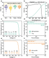
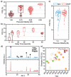
Self-assembled monolayers (SAMs) are becoming widely utilized as hole-selective layers in high-performance p-i-n architecture perovskite solar cells. Ultrasonic spray coating and airbrush coating are demonstrated here as effective methods to deposit MeO-2PACz; a carbazole-based SAM. Potential dewetting of hybrid perovskite precursor solutions from this layer is overcome using optimized solvent rinsing protocols. The use of air-knife gas-quenching is then explored to rapidly remove the volatile solvent from an MAPbI3 precursor film spray-coated onto an MeO-2PACz SAM, allowing fabrication of p-i-n devices with power conversion efficiencies in excess of 20%, with all other layers thermally evaporated. This combination of deposition techniques is consistent with a rapid, roll-to-roll manufacturing process for the fabrication of large-area solar cells.
Keywords: air-knife; gas-quenching; perovskite solar cells; scalable fabrication; self-assembled monolayers; spray coating.
© 2022 The Authors. Advanced Science published by Wiley-VCH GmbH.
Conflict of interest statement
D.G.L. is a director of the materials science company Ossila that retails materials and equipment for thin film fabrication, including for research and development of perovskite photovoltaics.
Figures


References
-
- NREL , Best Research‐Cell Efficiency Chart. https://www.nrel.gov/pv/cell-efficiency.html (accessed: August 2021).
-
- Diekmann J., Caprioglio P., Futscher M. H., Le Corre V. M., Reichert S., Jaiser F., Arvind M., Toro L. P., Gutierrez‐Partida E., Peña‐Camargo F., Deibel C., Ehrler B., Unold T., Kirchartz T., Neher D., Stolterfoht M., Sol. RRL 2021, 5, 2100219.
-
- Stolterfoht M., Wolff C. M., Márquez J. A., Zhang S., Hages C. J., Rothhardt D., Albrecht S., Burn P. L., Meredith P., Unold T., Neher D., Nat. Energy 2018, 3, 847.
-
- Perini C. A. R., Doherty T. A. S., Stranks S. D., Correa‐Baena J. P., Hoye R. L. Z., Joule 2021, 5, 1024.
-
- Bush K. A., Palmstrom A. F., Yu Z. J., Boccard M., Cheacharoen R., Mailoa J. P., McMeekin D. P., Hoye R. L. Z. Z., Bailie C. D., Leijtens T., Peters I. M., Minichetti M. C., Rolston N., Prasanna R., Sofia S., Harwood D., Ma W., Moghadam F., Snaith H. J., Buonassisi T., Holman Z. C., Bent S. F., McGehee M. D., Nat. Energy 2017, 2, 17009.
Grants and funding
LinkOut - more resources
Full Text Sources
Other Literature Sources
