. 2022 Apr;69(4):1428-1441.
doi: 10.1109/TUFFC.2022.3150746. Epub 2022 Mar 30.

Dual-Resonance (16/32 MHz) Piezoelectric Transducer With a Single Electrical Connection for Forward-Viewing Robotic Guidewire

Dual-Resonance (16/32 MHz) Piezoelectric Transducer With a Single Electrical Connection for Forward-Viewing Robotic Guidewire

Graham C Collins et al. IEEE Trans Ultrason Ferroelectr Freq Control. 2022 Apr.

Abstract

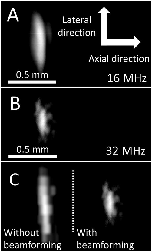
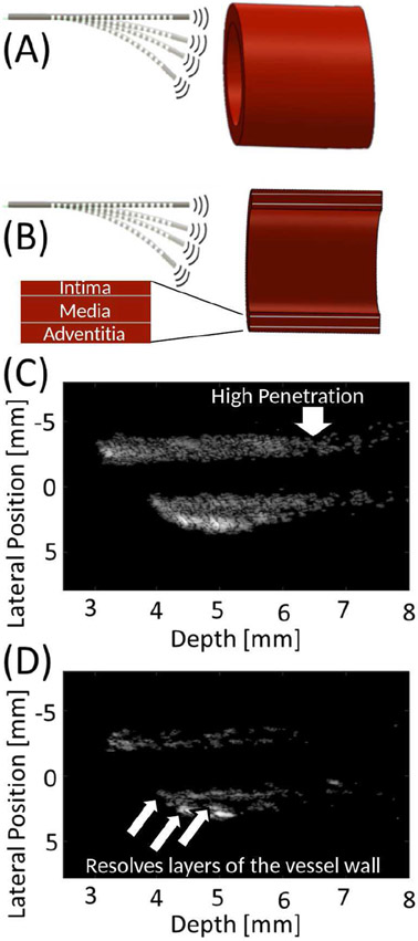
Peripheral artery disease (PAD) affects more than 200 million people globally. Minimally invasive endovascular procedures can provide relief and salvage limbs while reducing injury rates and recovery times. Unfortunately, when a calcified chronic total occlusion is encountered, ~25% of endovascular procedures fail due to the inability to advance a guidewire using the view provided by fluoroscopy. To enable a sub-millimeter, robotically steerable guidewire to cross these occlusions, a novel single-element, dual-band transducer is developed that provides simultaneous multifrequency, forward-viewing imaging with high penetration depth and high spatial resolution while requiring only a single electrical connection. The design, fabrication, and acoustic characterization of this device are described, and proof-of-concept imaging is demonstrated in an ex vivo porcine artery after integration with a robotically steered guidewire. Measured center frequencies of the developed transducer were 16 and 32 MHz, with -6 dB fractional bandwidths of 73% and 23%, respectively. When imaging a 0.2-mm wire target at a depth of 5 mm, measured -6 dB target widths were 0.498 ± 0.02 and 0.268 ± 0.01 mm for images formed at 16 and 32 MHz, respectively. Measured SNR values were 33.3 and 21.3 dB, respectively. The 3-D images of the ex vivo artery demonstrate high penetration for visualizing vessel morphology at 16 MHz and ability to resolve small features close to the transducer at 32 MHz. Using images acquired simultaneously at both frequencies as part of an integrated forward-viewing, guidewire-based imaging system, an interventionalist could visualize the best path for advancing the guidewire to improve outcomes for patients with PAD.


Figures

figure 1.
figure 1.
(A) Cross-sectional view of fabrication process showing bulk material removal, cutting of isolation notches, metallization, and addition of an attenuating backing. (B) 3D illustration showing the thick, low-frequency outer pillar, the isolation notch, and the thin, high-frequency pillar.
Fig. 2.
Fig. 2.
Transmitted acoustic pressure for A) the low-frequency pillar alone, B) the low-frequency component of the dual-frequency design, C) the high-frequency pillar alone, and D) the high-frequency component of the dual-frequency design.
Fig. 3.
Fig. 3.
Simulated transmitted pressure fields for the (A) low and (B) high-frequency bands, and simulated impulse responses displaying the (C) combined, (D) low frequency, and (E) high frequency signals.
Fig. 4.
Fig. 4.
(A) Confocal microscope image and (B) height profile of the fabricated dual-resonant component (diameter 0.89 mm for compatibility with a standard 0.035” guidewire). The color indicates the height, showing the high outer pillar, the low isolation notch, and the inner pillar with intermediate height.
Fig. 5.
Fig. 5.
(A) Photograph of the integrated robotic guidewire imaging system. The novel transducer with a single electrical connection is fixed on the tip of the robotic guidewire. (B) shows a focused view of the transducer fixed to the guidewire tip.
Fig. 6.
Fig. 6.
Magnitude (blue) and phase (red) of electrical impedance measured in air for the developed transducer with both low and high frequency resonances.
Fig. 7.
Fig. 7.
(A) Low and (B) high-frequency impulse responses of the fabricated transducer in the time and frequency domains.
Fig. 8.
Fig. 8.
B-mode images of a 0.2 mm wire target at a depth of 5 mm formed at (A) 16 MHz and (B) 32 MHz with the dual-band transducer (15 dB dynamic range). (C) Comparing the high-frequency image without (left) and with (right) beamforming shows that the −6 dB target width decreased by a factor of 2.3 with SAF. Scale is constant in A-C, and axial and lateral dimensions (indicated in A) are displayed with equal scale.
Fig. 9.
Fig. 9.
B-mode images of a speckle-producing phantom formed using the (A) low and (B) high-frequency band of the dual-band transducer. While low-frequency imaging allows for greater penetration, high-frequency imaging shows higher spatial resolution. Images are displayed with dynamic ranges of 45 and 35 dB, respectively. Inlays in (B) with no beamforming (i) and with synthetic aperture beamforming (ii) show improved SNR and higher spatial resolution with beamforming.
Fig. 10.
Fig. 10.
(A) Illustration of vessel orientation relative to the guidewire-based imaging system during acquisition of ex vivo porcine artery data, including (B) cross sectional view seen during imaging. B-mode image of vessel cross section acquired using (C) low and (D) high-frequency band of the dual-frequency transducer. Images in (C) and (D) are displayed with 40 and 30 dB dynamic range, respectively.
Fig. 11.
Fig. 11.
Reconstructed 3D volumes of ex vivo porcine arteries images acquired with the developed transducer are shown for five different angles (top to bottom) for (A) 16 MHz only, (B) 32 MHz only, (C) combined with 16 MHz data in gray and 32 MHz data in blue, and (D) fused 16 and 32 MHz data using a weighted sum. The transducer is positioned looking into the artery, i.e. at the top looking down for the 0° view. Enlarged views of (C) at 0° and 106° are provided to emphasize advantages of 16 and 32 MHz images, which provide high penetration and high spatial resolution, respectively.

References

    1. Nehler MR et al., “Epidemiology of peripheral arterial disease and critical limb ischemia in an insured national population,” Journal of Vascular Surgery, vol. 60, no. 3, pp. 686–695.e2, Sep. 2014, doi: 10.1016/j.jvs.2014.03.290. - DOI - PubMed
    1. Song P et al., “Global, regional, and national prevalence and risk factors for peripheral artery disease in 2015: an updated systematic review and analysis,” The Lancet Global Health, vol. 7, no. 8, pp. e1020–e1030, Aug. 2019, doi: 10.1016/S2214-109X(19)30255-4. - DOI - PubMed
    1. Fowkes FGR, Aboyans V, Fowkes FJI, McDermott MM, Sampson UKA, and Criqui MH, “Peripheral artery disease: epidemiology and global perspectives,” Nature Reviews Cardiology, vol. 14, no. 3, pp. 156–170, Mar. 2017, doi: 10.1038/nrcardio.2016.179. - DOI - PubMed
    1. Navneet Narula et al., “Pathology of Peripheral Artery Disease in Patients With Critical Limb Ischemia,” Journal of the American College of Cardiology, vol. 72, no. 18, pp. 2152–2163, Oct. 2018, doi: 10.1016/j.jacc.2018.08.002. - DOI - PubMed
    1. Rogers JH and Laird JR, “Overview of new technologies for lower extremity revascularization,” Circulation, vol. 116, no. 18, pp. 2072–2085, 2007. - PubMed

Publication types