. 2022 Feb 1;55(Pt 1):1-13.
doi: 10.1107/S1600576721011079.

Co-flow injection for serial crystallography at X-ray free-electron lasers

Diandra Doppler  1   2 Mohammad T Rabbani  1   2 Romain Letrun  3 Jorvani Cruz Villarreal  1   2 Dai Hyun Kim  1   2 Sahir Gandhi  1   2 Ana Egatz-Gomez  1   2 Mukul Sonker  1   2 Joe Chen  4 Faisal H M Koua  5 Jayhow Yang  2 Mohamed Youssef  5 Victoria Mazalova  5 Saša Bajt  6   7 Megan L Shelby  8 Matt A Coleman  8 Max O Wiedorn  5   6   9 Juraj Knoska  5 Silvan Schön  5 Tokushi Sato  3 Mark S Hunter  10 Ahmad Hosseinizadeh  11 Christopher Kuptiz  10 Reza Nazari  2   4 Roberto C Alvarez  2   4 Konstantinos Karpos  2   4 Sahba Zaare  2   4 Zachary Dobson  1   2 Erin Discianno  2 Shangji Zhang  1   2 James D Zook  1   2 Johan Bielecki  3 Raphael de Wijn  3 Adam R Round  3   12 Patrik Vagovic  3   5 Marco Kloos  3 Mohammad Vakili  3 Gihan K Ketawala  1   2 Natasha E Stander  1   2 Tien L Olson  1   2 Katherine Morin  2 Jyotirmory Mondal  13 Jonathan Nguyen  1   2 José Domingo Meza-Aguilar  2   3 Gerdenis Kodis  1   2   4 Sara Vaiana  4 Jose M Martin-Garcia  2   14 Valerio Mariani  5 Peter Schwander  11 Marius Schmidt  11 Marc Messerschmidt  1   2 Abbas Ourmazd  11 Nadia Zatsepin  2   4   15 Uwe Weierstall  2   4 Barry D Bruce  13 Adrian P Mancuso  3   15 Thomas Grant  16 Anton Barty  5   7   17 Henry N Chapman  5   6   9 Matthias Frank  8 Raimund Fromme  1   2 John C H Spence  2   4 Sabine Botha  2   4 Petra Fromme  1   2 Richard A Kirian  2   4 Alexandra Ros  1   2
Affiliations

Co-flow injection for serial crystallography at X-ray free-electron lasers

Diandra Doppler et al. J Appl Crystallogr. .

Abstract

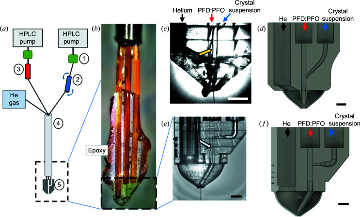
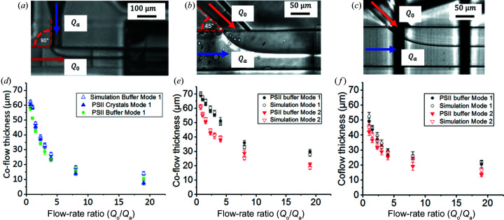
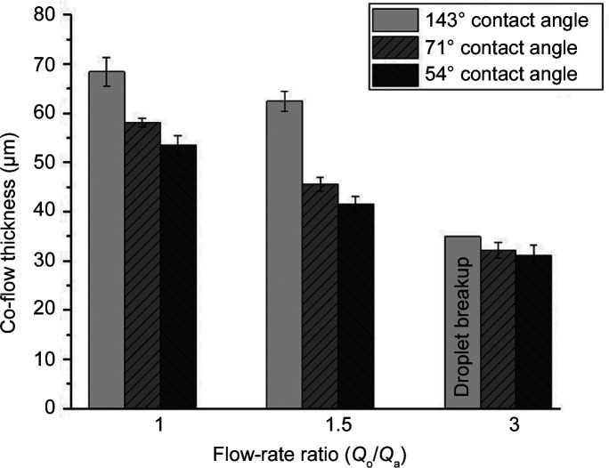
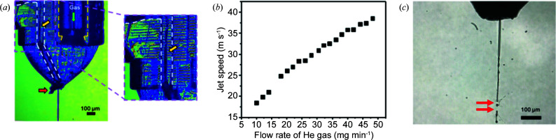
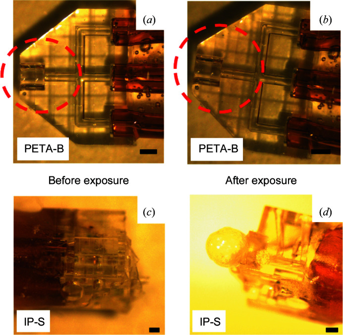
Serial femtosecond crystallography (SFX) is a powerful technique that exploits X-ray free-electron lasers to determine the structure of macro-molecules at room temperature. Despite the impressive exposition of structural details with this novel crystallographic approach, the methods currently available to introduce crystals into the path of the X-ray beam sometimes exhibit serious drawbacks. Samples requiring liquid injection of crystal slurries consume large quantities of crystals (at times up to a gram of protein per data set), may not be compatible with vacuum configurations on beamlines or provide a high background due to additional sheathing liquids present during the injection. Proposed and characterized here is the use of an immiscible inert oil phase to supplement the flow of sample in a hybrid microfluidic 3D-printed co-flow device. Co-flow generation is reported with sample and oil phases flowing in parallel, resulting in stable injection conditions for two different resin materials experimentally. A numerical model is presented that adequately predicts these flow-rate conditions. The co-flow generating devices reduce crystal clogging effects, have the potential to conserve protein crystal samples up to 95% and will allow degradation-free light-induced time-resolved SFX.

Keywords: 3D printing; X-ray free-electron lasers; XFELs; microfluidic devices; sample consumption; serial crystallography; viscous media.


Figures

Figure 1
Figure 1
(a) The experimental setup of the co-flow generator at the EuXFEL (not to scale). (1) Flow-rate sensors, (2) crystal suspension reservoir mounted in the rotating anti-settler device, (3) oil reservoir, (4) nozzle rod and (5) hybrid device (3D-printed device with integrated co-flow generator and GDVN) mounted on the end of the nozzle rod. Black lines indicate capillary tubing or fused silica capillaries for fluid and gas transport. (b) The assembled hybrid device mounted in the nozzle rod. The co-flow/nozzle hybrid is located at the very end of the one gas and two fluidic lines connected to the fused silica capillaries through epoxy. (c) An image of the assembled Y-junction device. Co-flow is generated as indicated by the interface between the two phases (see yellow arrow). (d) A schematic drawing of the Y-junction device for co-flow formation designed in Fusion 360. (e) An image of the T-junction hybrid device, showing the oil–sample co-flow running (marked with a white arrow) and the jet leaving the nozzle. (f) A schematic drawing of the T-junction device for co-flow formation designed in Fusion 360. The scale bars represent 200 µm in panels (c)–(f).
Figure 2
Figure 2
(a) Bright-field microscopy image of the T-junction geometry 3D-printed with IP-S photoresist in mode 1 with a flow-rate ratio of 1. (b) Bright-field microscopy image of the Y-junction geometry 3D-printed with IP-S photoresist in mode 2 with a flow-rate ratio of 4. (c) Bright-field microscopy image of the Y-junction geometry 3D-printed with PETA-B photoresist in mode 2 with a flow-rate ratio of 1. (d) Co-flow thickness of the T-junction device with PSII crystal in the buffer (filled green circles), PSII buffer only (filled blue triangles) and simulation (open blue triangles). The error bars indicate the standard deviation of the co-flow thickness. The devices used to test these conditions were made of IP-S photoresist. (e) The co-flow thickness of the Y-junction with PSII buffer in mode 1 (filled black circles) and mode 2 (filled red triangles) compared with the numerical simulation in mode 1 (open black circles) and simulation mode 2 (open red triangles). The error bars indicate the standard deviation of the co-flow thickness. The devices used to test these conditions were made of IP-S photoresist. (f) The co-flow thickness of the Y-junction with PSII buffer in mode 1 (filled black circles) and mode 2 (filled red triangles) compared with simulation mode 1 (open black circles) and simulation mode 2 (open red triangles). The error bars indicate the standard deviation of the co-flow thickness. The devices used to test these conditions were made of PETA-B photoresist.
Figure 3
Figure 3
Co-flow thickness in the T-junction with PSII buffer in mode 1 at different flow rates and contact angles. Co-flow thickness was estimated for contact angles of 143, 71 and 54°. The co-flow thickness decreases with decreasing contact angle. For a flow-rate ratio of 3, instead of co-flow, droplet generation was observed for a hydrophobic condition (contact angle of 143°). The error bars indicate the standard deviation of the co-flow thickness.
Figure 4
Figure 4
(a) An image of an IP-S co-flow device installed in the SPB/SFX chamber at the EuXFEL. The enlarged image shows the boundary of the two immiscible phases indicated by the yellow arrow. (b) Jet speed versus flow rate of He gas as investigated for PSII buffer obtained from a PETA-B co-flow hybrid. (c) Optical microscopy image of a jet containing protein crystals recorded in the SPB/SFX chamber (Q o of 15 µl min−1, Q a of 5 µl min−1 and He flow rate of 20 mg min−1). Jet imaging was performed by optical laser illumination after the second X-ray pulse in the bunch train to achieve this image. Highlighted with red arrows are the positions of where consecutive XFEL pulses impact the jet.
Figure 5
Figure 5
(a), (b) An exposure test of a 3D-printed PETA-B device (for demonstration purposes, a microfluidic mixer with similar device thickness and channel cross section to the co-flow hybrid devices) with a nanosecond 532 nm laser at 360 mJ cm−2 fluence in air for 10 min. The beam diameter was 1 mm and it was aligned over the device, as indicated by the red dashed circle corresponding approximately to the overlap spot in the EuXFEL experiment (with a distance of 800 µm from the nozzle tip into the device overlapping with the circular laser spot). (b) No visible damage was observed after laser illumination. (c), (d) A 3D-printed IP-S injection device (for demonstration purposes, a microfluidic droplet generator with similar device thickness and channel cross section to the co-flow hybrid devices) was employed for testing. Representative images are shown of IP-S devices (c) before and (d) after laser exposure (200 mJ cm−2 for 15 min). The IP-S devices show bubble formation at the nozzle exit of the device, indicating damage after laser illumination. Scale bars represent 200 µm in panels (a)–(d).
Figure 6
Figure 6
A representative diffraction pattern of PSII crystals delivered with the 3D-printed PETA-B co-flow hybrid device with a resolution better than 5 Å.

References

    1. Abramoff, M. D., Magalhaes, P. J. & Ram, S. J. (2004). Biophoton. Int. 11, 36–42.
    1. Adrian, R. (1991). Annu. Rev. Fluid Mech. 23, 261–304.
    1. Allahgholi, A., Becker, J., Delfs, A., Dinapoli, R., Goettlicher, P., Greiffenberg, D., Henrich, B., Hirsemann, H., Kuhn, M., Klanner, R., Klyuev, A., Krueger, H., Lange, S., Laurus, T., Marras, A., Mezza, D., Mozzanica, A., Niemann, M., Poehlsen, J., Schwandt, J., Sheviakov, I., Shi, X., Smoljanin, S., Steffen, L., Sztuk-Dambietz, J., Trunk, U., Xia, Q., Zeribi, M., Zhang, J., Zimmer, M., Schmitt, B. & Graafsma, H. (2019). J. Synchrotron Rad. 26, 74–82. - PMC - PubMed
    1. Ananyev, G., Roy-Chowdhury, S., Gates, C., Fromme, P. & Dismukes, G. C. (2019). ACS Catal. 9, 1396–1407.
    1. Atha, D. H. & Ingham, K. C. (1981). J. Biol. Chem. 256, 12108–12117. - PubMed