. 2021 Aug 15;11(8):948.
doi: 10.3390/cryst11080948.

Engineering Crystal Packing in RNA-Protein Complexes II: A Historical Perspective from the Structural Studies of the Spliceosome

Affiliations

Engineering Crystal Packing in RNA-Protein Complexes II: A Historical Perspective from the Structural Studies of the Spliceosome

Adelaine Kwun-Wai Leung et al. Crystals (Basel). .

Abstract

Cryo-electron microscopy has greatly advanced our understanding of how the spliceosome cycles through different conformational states to conduct the chemical reactions that remove introns from pre-mRNA transcripts. The Cryo-EM structures were built upon decades of crystallographic studies of various spliceosomal RNA-protein complexes. In this review we give an overview of the crystal structures solved in the Nagai group, utilizing many of the strategies to design crystal packing as described in the accompanying paper.

Keywords: RNA-protein complexes; crystallization; spliceosome.


Conflict of interest statement

Conflicts of Interest: The authors declare no conflict of interest.

Figures

Figure 1
Figure 1
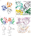
(A) The spliceosome in different catalytic states as revealed by Cryo-EM. Shown are the schematics of the pre-mRNA and the silhouettes of each splicing complex from Cryo-EM structures. Proteins involved in remodeling the spliceosome are not included. NTC/NTR are protein complexes that help sculpt the active site of the spliceosome together with U2, U5, and U6 snRNPs. Prespliceosome (E, A complex): U1 snRNP recognizes the 5′ splice site (5′ss) forming the E complex. U2 snRNP recognizes and the invariant adenosine on the branch point (purple box) forming the A complex. Precatalytic spliceosome (Pre-B, B Complex): The U4/U6.U5 tri-snRNP enters to form the Pre-B complex and the helicase-dependent dissociation of U1 snRNP generates the B complex. Activated spliceosome (Bact-Complex, B*, C, C*): Further helicase-dependent remodeling releases U4 snRNA and U4/U6 di-snRNP proteins, which allow U6 snRNA to refold with U2 snRNA and the pre-mRNA into a catalytic active conformation, allowing the 2-step splicing reactions to occur. In step 1, the 2-OH of the branch point adenosine attacks the phosphorous of the 5′ss to form the lariat intron. In step 2, the 3′-OH of the cleaved 5′ss attacks the phosphorous of the 3′ss to form the ligated mRNA. Postspliceosomal complex (P complex): Helicase-dependent release of the ligated exons. Disassembly of the spliceosome: Helicase-dependent release of intron lariat and recycling of U snRNPs. (B) Secondary structures of the U snRNAs and a summary of crystal structures of spliceosomal RNA-protein complexes determined by the Nagai lab from 1994 to 2015. The U snRNPs share seven common Sm proteins that assemble on the Sm site (in red solid box). Blue dots represent the tri-methylguanosine cap. U6 snRNA does not have an Sm site but instead contains a U-rich tail that is bound by seven paralogs of the Sm proteins (LSm 2–8). U1A/U1-SLII: the hairpin loop II of U1 snRNA bound to the U1A protein was determined to be 1.92 Å in 1994. U2′AB″/U2-SLIV: the hairpin loop IV of U2 snRNA bound to the U2 specific proteins U2A and U2B was determined to be 2.38 Å in 1998. U4 core: the core domain structure of the U4 snRNP containing two stem loops flanking the Sm site and seven Sm proteins was determined in stages to the final refined structure at 3.6 Å (2005, 2011, 2016). U1 snRNP: The first U1 snRNP structure was determined without U1A and the hairpin loop II to be 5.5 Å in 2009. The minimal snRNP, with the four-way junction replaced by a stem loop and the N-terminal U1-70K peptide fused to SmD1, which was determined to be 3.3 Å in 2015. U1A70K: the hairpin loop I of U1 snRNA bound to U1-70K was determined to be 2.50 Å in 2015.
Figure 2
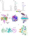
Figure 2. Hairpin structures of U1-SLII and U2-SLIV. (A-B) U1A/U1-SLII (PDB:1URN).
(A) Three NCS copies related by a 3-fold axis are present in the asymmetric unit. The complex is named after the chain ID. A, B, C: U1A and P, Q, R: U1-SLII. Only protein-protein interactions are observed between the NCS complexes. (B) Close up of the protein-RNA interaction between the NCS copies. The Y31H splits open the end pair (A1:U20) of the stem loop of P/A. (C-D) U2A′B″/U1-SLIV (PDB:1A9N). (C) Two NCS copies are present in the asymmetric unit. The complex is named after the chain ID. A, C:U2-A′; B, D:U2-B″; Q, R:U2-IV. Interactions between U2-A′ are the only contacts between the NCS complexes. (D) The sequence A14, C15, C16 at the 3′ end of the loop forms a step ladder structure. A14 forms a Hoogsteen to WC base pair with the 3′ sticky U23. (E) The hairpin loop sequence of U1-SLII and U2-SLIV. The 5′ 6 nt loop sequence (in red) are identical between the two RNAs whereas the 3′ loop sequence confers binding specificity. Engineered sequence is colored in gray.
Figure 3
Figure 3
(A) Native sequence of the 3′ end of the U4 snRNA. (B) U4 construct used in the crystal structure. Highlighted in green is the GAAA tetraloop (TL), in purple is another stable GRNA tetraloop, and in blue is the GAAA receptor (TLR). The Sm site nucleotides that interact around the inner pore of the core ring is highlighted in red. Each Sm site nucleotide interacts in the binding pocket of the Sm protein depicted underneath. (C) One complex of the U4 snRNP core domain. The 5′ SLII carrying the GAAA tetraloop is located on the flat face of the core ring and the 3′ SLIII carrying the TLR is located on the tapered face of the core ring. The 5′ SLII bends over the D2/D1/B sector of the ring. The surface color represents the electric potential of the surface (blue: positive, red: negative). (D) Superposition of the 12 NCS copies showing the stem loops have variable tilt angles relative to the plane of the core ring. The plane and the axes were drawn using Chimera. The plane was drawn by selecting the first residue after helix 1 of each Sm-fold. The orientation of the superposition is adjusted slightly from that shown in Figure A to better highlight the tilt angles of the RNA stems. (E) One example of the TL/TLR interactions between symmetry pairs. Twelve complexes packed as six distinct pairs are in the asymmetric unit. On the flat face, the 5′ TL of complex A interacts with the 3′ TLR of the NCS complex B. On the tapered face, the 3′ TLR of complex A interacts with another complex B related by crystallographic symmetry. (F) The TL/TLR interactions combines the core rings to pack rim-to-rim along the c axis.
Figure 4
Figure 4
The 3.3 Å Cryo-EM structure of Pre-B spliceosome captured before U1 snRNP dissociates (PDB:6QX9). The model is depicted in ribbons representation. The D2/D1/B sector of the four core domains is colored in red and D3/G/E/F is colored in bright green; all other protein components are colored in grey. U1 snRNA (yellow), U2 snRNA (purple), U4 snRNA (light blue), U5 snRNA (dark blue), U6 (orange), and pre-mRNA (cyan). The functionally important RNA structures all bend toward the D2/D1/B sector. Thus, the direction of the RNA backbone 5′ to the Sm site is significant in positioning structural elements that eventually form the catalytic active site.
Figure 5
Figure 5
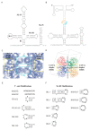
(A) Native sequence of U1 snRNA. (B) Construct used to crystallize the first U1 snRNP. The base pairing between the kissing loop is depicted in cyan and orange. (C) Experimental electron density map of U1 snRNP at 5.5 Å. Density for the major and minor grooves of the kissing loop helices and the U1/5′ss helices is clear. (D) The packing arrangement of U1 snRNP for the P1 crystal form (PDB:3CW1). The four NCS complexes are related by three orthogonal 2-fold symmetry axes (shown as gray rods). The kissing loop interactions are formed along one 2-fold. The 5′ strand of the U1 snRNA base pair with its NCS-related partner along another 2-fold axis, mimicking the U1/5′ss interaction. (E,F) Summary of the next series of constructs modified to improve diffraction quality of the P1 crystal form. Examples of constructs with modified 5′ end (E) and modified SL-III (F).
Figure 6
Figure 6
(A) The packing arrangement of the minimal U1 snRNP in the P212121 crystal form (PDB:4PJO). Four NCS complexes (Complex 1–4) are present in the asymmetric unit. Complexes 3 and 4 are located behind the page. Only protein-protein interactions are observed between the NCS complexes. Kissing loop interactions (KL) and end-to-end packing of the 5′ss/U1RNA helix (H) are the main crystal packing interactions occurring in this crystal form. Two sets of interactions are depicted in this figure. Complex 1 forms a KL interaction with the symmetry-related Complex 2 and a continuous duplex stacking with the symmetry-related Complex 3. Complex 2 forms a KL interaction with the symmetry-related Complex 1 and a continuous duplex stacking with the symmetry-related Complex 4. An example of this cyclical packing arrangement is summarized in C. (B) An example of the KL interaction formed between Complex 1 and the symmetry-related Complex 2. Unlike the original DIS kissing loop complex crystal structure (PDB:1XPE), in which two bulged purines form crystal contacts lateral to the stems, only one purine is bulged out to stack with the equivalent nucleotide. The other purine forms a non-canonical base pair with the unpaired A 3′ to the 6-nt kissing loop complex. (C) An example of the packing arrangement involving kissing loops (KL) and continuous end-to-end stacking of the 5′ss/5′U1 duplex (H). Complex 1 interacts with 2–4 in the NCS via protein contacts only. Each NCS complex makes the same packing arrangement with the same set of symmetry-related complexes. The text color for each complex is the same as those depicted in A. Text color in black are complexes that are not shown in A. (D) Secondary structure of the RNA construct used in the P212121 crystal form.

References

    1. Wilkinson ME, Charenton C, Nagai K. RNA Splicing by the Spliceosome. Annu Rev Biochem. 2020;89:359–388. doi: 10.1146/annurev-biochem-091719-064225. - DOI - PubMed
    1. Kuhlbrandt W. Biochemistry. The resolution revolution. Science. 2014;343:1443–1444. doi: 10.1126/science.1251652. - DOI - PubMed
    1. Crowther RA. In: Methods in Enzymology. Crowther RA, editor. Vol. 579. Academic Press; Cambridge, MA, USA: 2016. Preface; pp. xiii–xx. - PubMed
    1. Kastner B, Will CL, Stark H, Luhrmann R. Structural Insights into Nuclear pre-mRNA Splicing in Higher Eukaryotes. Cold Spring Harb Perspect Biol. 2019;11:a032417. doi: 10.1101/cshperspect.a032417. - DOI - PMC - PubMed
    1. Plaschka C, Newman AJ, Nagai K. Structural Basis of Nuclear pre-mRNA Splicing: Lessons from Yeast. Cold Spring Harb Perspect Biol. 2019;11:a032391. doi: 10.1101/cshperspect.a032391. - DOI - PMC - PubMed

LinkOut - more resources