

Coarse Grained Modeling of Multiphase Flows with Surfactants
- PMID: 35160531
- PMCID: PMC8840224
- DOI: 10.3390/polym14030543
Coarse Grained Modeling of Multiphase Flows with Surfactants
Abstract
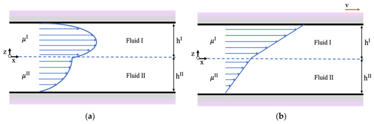
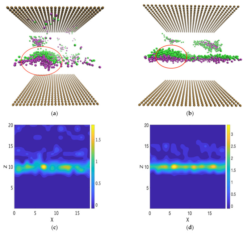
Coarse-grained modeling methods allow simulations at larger scales than molecular dynamics, making it feasible to simulate multifluid systems. It is, however, critical to use model parameters that represent the fluid properties with fidelity under both equilibrium and dynamic conditions. In this work, dissipative particle dynamics (DPD) methods were used to simulate the flow of oil and water in a narrow slit under Poiseuille and Couette flow conditions. Large surfactant molecules were also included in the computations. A systematic methodology is presented to determine the DPD parameters necessary for ensuring that the boundary conditions were obeyed, that the oil and water viscosities were represented correctly, and that the velocity profile for the multifluid system agreed with the theoretical expectations. Surfactant molecules were introduced at the oil-water interface (sodium dodecylsulfate and octaethylene glycol monododecyl ether) to determine the effects of surface-active molecules on the two-phase flow. A critical shear rate was found for Poiseuille flow, beyond which the surfactants desorbed to form the interface forming micelles and destabilize the interface, and the surfactant-covered interface remained stable under Couette flow even at high shear rates.
Keywords: coarse grained computations; multiphase flow; oil–water interfaces; surfactants.
Conflict of interest statement
The authors declare no conflict of interest. The funders had no role in the design of the study; in the collection, analyses, or interpretation of data; in the writing of the manuscript, or in the decision to publish the results.
Figures


Similar articles
-
Janus Nanoparticle and Surfactant Effects on Oil Drop Migration in Water under Shear.J Phys Chem B. 2022 Aug 25;126(33):6314-6323. doi: 10.1021/acs.jpcb.2c03670. Epub 2022 Aug 15. J Phys Chem B. 2022. PMID: 35969639
-
Oil-water interfaces with surfactants: A systematic approach to determine coarse-grained model parameters.J Chem Phys. 2018 May 28;148(20):204704. doi: 10.1063/1.5022798. J Chem Phys. 2018. PMID: 29865808
-
Comprehensive review of the interfacial behavior of water/oil/surfactant systems using dissipative particle dynamics simulation.Adv Colloid Interface Sci. 2022 Nov;309:102774. doi: 10.1016/j.cis.2022.102774. Epub 2022 Sep 15. Adv Colloid Interface Sci. 2022. PMID: 36152373 Review.
-
Effect of Janus particles and non-ionic surfactants on the collapse of the oil-water interface under compression.J Colloid Interface Sci. 2022 Mar;609:158-169. doi: 10.1016/j.jcis.2021.11.160. Epub 2021 Nov 28. J Colloid Interface Sci. 2022. PMID: 34894550
-
Dissipative particle dynamics simulations in colloid and Interface science: a review.Adv Colloid Interface Sci. 2021 Dec;298:102545. doi: 10.1016/j.cis.2021.102545. Epub 2021 Oct 14. Adv Colloid Interface Sci. 2021. PMID: 34757286 Review.
Cited by
-
Prediction of the aggregation rate of nanoparticles in porous media in the diffusion-controlled regime.Sci Rep. 2024 Jan 22;14(1):1916. doi: 10.1038/s41598-023-50643-x. Sci Rep. 2024. PMID: 38253573 Free PMC article.
-
Polymers in Physics, Chemistry and Biology: Behavior of Linear Polymers in Fractal Structures.Polymers (Basel). 2024 Dec 2;16(23):3400. doi: 10.3390/polym16233400. Polymers (Basel). 2024. PMID: 39684144 Free PMC article. Review.
References
-
- Soares E.J., Thompson R.L. Flow regimes for the immiscible liquid–liquid displacement in capillary tubes with complete wetting of the displaced liquid. J. Fluid Mech. 2009;641:63–84. doi: 10.1017/S0022112009991546. - DOI
-
- Zhao H., Ning Z., Kang Q., Chen L., Zhao T. Relative permeability of two immiscible fluids flowing through porous media determined by lattice Boltzmann method. Int. Commun. Heat Mass Transf. 2017;85:53–61. doi: 10.1016/j.icheatmasstransfer.2017.04.020. - DOI
-
- Li J., Sheeran P.S., Kleinstreuer C. Analysis of multi-layer immiscible fluid flow in a microchannel. J. Fluids Eng. 2011;133:111202. doi: 10.1115/1.4005134. - DOI
-
- Gaddam A., Garg M., Agrawal A., Joshi S.S. Modeling of liquid–gas meniscus for textured surfaces: Effects of curvature and local slip length. J. Micromech. Microeng. 2015;25:125002. doi: 10.1088/0960-1317/25/12/125002. - DOI
Grants and funding
LinkOut - more resources
Full Text Sources
