

An Investigation of a New Parameter Based on the Plastic Strain Gradient to Characterize Composite Constraint around the Crack Front at a Low Temperature
- PMID: 35160826
- PMCID: PMC8836885
- DOI: 10.3390/ma15030881
An Investigation of a New Parameter Based on the Plastic Strain Gradient to Characterize Composite Constraint around the Crack Front at a Low Temperature
Abstract
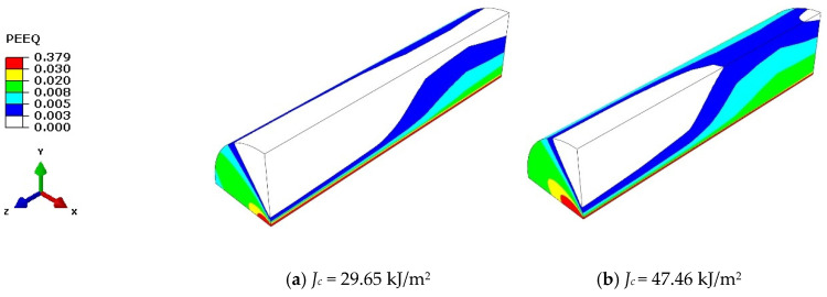
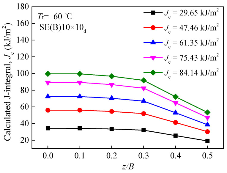
Stress corrosion cracking (SCC) is an important destruction form of materials such as stainless steel, nickel-based alloy and their welded components in nuclear reactor pressure vessels and pipes. The existing popular quantitative prediction models of SCC crack growth rate are mainly influenced by fracture toughness values KJc or Jc. In particular, the composite constraint, containing the in-plane constraints and out-of-plane constraints around the crack front, has a significant influence on the fracture toughness of structures in nuclear power plants. Since the plastic strain gradient is a characterization parameter of the quantitative prediction model for crack growth rate, it may be a characterization parameter of composite constraint. On the basis of the experimental data at a low temperature of alloy steel 22NiMoCr3-7 used in nuclear pressure vessels, the gradient of equivalent plastic strain DPEEQ around the crack fronts at different constraint levels was calculated using the finite element method, which introduces a new non-dimensional constraint parameter Dp, to uniformly characterize the in-plane and out-of-plane constraint effects. Compared with constraint parameters APEEQ or Ap, the process of obtaining parameters DPEEQ or Dp is much simpler and easier. In a wide range, a single correlation curve was drawn between parameter Dp and normalized fracture toughness values KJc/Kref or Jc/Jref of specimens at a low or high constraint level. Therefore, regardless of whether the constraint levels of the structures or standard specimens are low or high, constraint parameter Dp can be used to measure their fracture toughness. To build an evaluation method that has structural integrity and safety while containing the composite constraint effects, in addition to accurate theoretical interpretation, further verification experiments, numerical simulations and detailed discussions are still needed.
Keywords: composite constraint; fracture toughness; quantitative prediction; strain gradient; stress corrosion cracking.
Conflict of interest statement
The authors declare no conflict of interest.
Figures


Similar articles
-
Effects of the Crack Tip Constraint on the Fracture Assessment of an Al 5083-O Weldment for Low Temperature Applications.Materials (Basel). 2017 Jul 18;10(7):815. doi: 10.3390/ma10070815. Materials (Basel). 2017. PMID: 28773179 Free PMC article.
-
Effects of Crack Tip Constraint on the Fracture Toughness Assessment of 9% Ni Steel for Cryogenic Application in Liquefied Natural Gas Storage Tanks.Materials (Basel). 2020 Nov 20;13(22):5250. doi: 10.3390/ma13225250. Materials (Basel). 2020. PMID: 33233654 Free PMC article.
-
Numerical Investigation of the Influence of Ultimate-Strength Heterogeneity on Crack Propagation and Fracture Toughness in Welded Joints.Materials (Basel). 2022 May 27;15(11):3814. doi: 10.3390/ma15113814. Materials (Basel). 2022. PMID: 35683113 Free PMC article.
-
Corrosion pitting and environmentally assisted small crack growth.Proc Math Phys Eng Sci. 2014 Sep 8;470(2169):20140254. doi: 10.1098/rspa.2014.0254. Proc Math Phys Eng Sci. 2014. PMID: 25197249 Free PMC article. Review.
-
Fracture Models and Effect of Fibers on Fracture Properties of Cementitious Composites-A Review.Materials (Basel). 2020 Dec 2;13(23):5495. doi: 10.3390/ma13235495. Materials (Basel). 2020. PMID: 33276552 Free PMC article. Review.
Cited by
-
Elastic-plastic fracture analysis of pressure pipelines with axial cracks based on the interaction integral method.PLoS One. 2024 Dec 26;19(12):e0301015. doi: 10.1371/journal.pone.0301015. eCollection 2024. PLoS One. 2024. PMID: 39724029 Free PMC article.
-
Prognosis methods of stress corrosion cracking under harsh environmental conditions.Heliyon. 2024 Feb 1;10(3):e25276. doi: 10.1016/j.heliyon.2024.e25276. eCollection 2024 Feb 15. Heliyon. 2024. PMID: 38863876 Free PMC article. Review.
-
Special Issue "Extreme Mechanics in Multiscale Analyses of Materials".Materials (Basel). 2023 Apr 5;16(7):2886. doi: 10.3390/ma16072886. Materials (Basel). 2023. PMID: 37049180 Free PMC article.
References
-
- Meng F.M., Wang J.Q., Han E.H., Shoji T., Ke W. Microstructure near scratch on alloy 690tt and stress corrosion induced by scratching. Acta Metall. Sin. 2011;47:839–846.
-
- Xue H., Ogawa K., Shoji T. Effect of welded mechanical heterogeneity on local stress and strain ahead of stationary and growing crack tips. Nucl. Eng. Des. 2009;239:628–640. doi: 10.1016/j.nucengdes.2008.12.024. - DOI
-
- Zhao L.Y., Cui Y.H., Yang F.Q., Xue H. Analysis on crack driving force at stress corrosion cracking tip induced by scratch in Nickel-based alloy. Rare Met. Mater. Eng. 2018;47:1399–1406. doi: 10.1016/S1875-5372(18)30141-3. - DOI
-
- Horn R.M., Gordon G.M., Ford F.P., Cowan R.L. Experience and assessment of stress corrosion cracking in L-grade stainless steel BWR internals. Nucl. Eng. Des. 1997;174:313–325. doi: 10.1016/S0029-5493(97)00131-3. - DOI
-
- Hohe J., Hebel J., Friedmann V., Siegele D. Probabilistic failure assessment of ferritic steels using the master curve approach including constraint effects. Eng. Fract. Mech. 2007;74:1274–1292. doi: 10.1016/j.engfracmech.2006.07.007. - DOI
Grants and funding
LinkOut - more resources
Full Text Sources
Research Materials
