

A Crack Propagation Method for Pipelines with Interacting Corrosion and Crack Defects
- PMID: 35161732
- PMCID: PMC8838264
- DOI: 10.3390/s22030986
A Crack Propagation Method for Pipelines with Interacting Corrosion and Crack Defects
Abstract
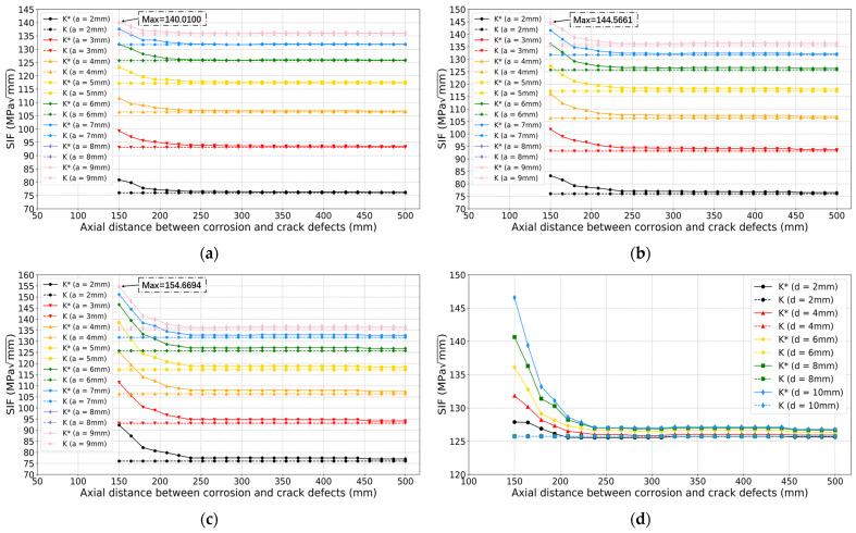
Corrosion and crack defects often exist at the same time in pipelines. The interaction impact between these defects could potentially affect the growth of the fatigue crack. In this paper, a crack propagation method is proposed for pipelines with interacting corrosion and crack defects. The finite element models are built to obtain the Stress Intensity Factors (SIFs) for fatigue crack. SIF interaction impact ratio is introduced to describe the interaction effect of corrosion on fatigue crack. Two approaches based on extreme gradient boosting (XGBoost) are proposed in this paper to predict the SIF interaction impact ratio at the deepest point of the crack defect for pipelines with interacting corrosion and crack defects. Crack size, corrosion size and the axial distance between these two defects are the factors that have an impact on the growth of the fatigue crack, and so they are considered as the input of XGBoost models. Based on the synthetic samples from finite element modeling, it has been proved that the proposed approaches can effectively predict the SIF interaction impact ratio with relatively high accuracy. The crack propagation models are built based on the proposed XGBoost models, Paris' law and corrosion growth model. Sensitivity analyses regarding corrosion initial depth and axial distance between defects are performed. The proposed method can support pipeline integrity management by linking the crack propagation model with corrosion size, crack size and the axial distance. The problem of how the interaction between corrosion and crack defects impacts crack defect growth is investigated.
Keywords: XGBoost; corrosion; fatigue crack; finite element; pipeline; stress intensity factor.
Conflict of interest statement
The authors declare no conflict of interest.
Figures


Similar articles
-
Adaptive Finite Element Modeling of Linear Elastic Fatigue Crack Growth.Materials (Basel). 2022 Oct 30;15(21):7632. doi: 10.3390/ma15217632. Materials (Basel). 2022. PMID: 36363222 Free PMC article.
-
Prediction of Corrosive Fatigue Life of Submarine Pipelines of API 5L X56 Steel Materials.Materials (Basel). 2019 Mar 28;12(7):1031. doi: 10.3390/ma12071031. Materials (Basel). 2019. PMID: 30925744 Free PMC article.
-
Corrosion-Fatigue Crack Growth in Plates: A Model Based on the Paris Law.Materials (Basel). 2017 Apr 22;10(4):439. doi: 10.3390/ma10040439. Materials (Basel). 2017. PMID: 28772798 Free PMC article.
-
A Robust Adaptive Mesh Generation Algorithm: A Solution for Simulating 2D Crack Growth Problems.Materials (Basel). 2023 Sep 29;16(19):6481. doi: 10.3390/ma16196481. Materials (Basel). 2023. PMID: 37834618 Free PMC article. Review.
-
Corrosion pitting and environmentally assisted small crack growth.Proc Math Phys Eng Sci. 2014 Sep 8;470(2169):20140254. doi: 10.1098/rspa.2014.0254. Proc Math Phys Eng Sci. 2014. PMID: 25197249 Free PMC article. Review.
Cited by
-
Elastic-plastic fracture analysis of pressure pipelines with axial cracks based on the interaction integral method.PLoS One. 2024 Dec 26;19(12):e0301015. doi: 10.1371/journal.pone.0301015. eCollection 2024. PLoS One. 2024. PMID: 39724029 Free PMC article.
-
Advanced Sensing, Fault Diagnostics, and Structural Health Management.Sensors (Basel). 2022 Nov 23;22(23):9087. doi: 10.3390/s22239087. Sensors (Basel). 2022. PMID: 36501788 Free PMC article.
References
-
- Vanaei H.R., Eslami A., Egbewande A. A review on pipeline corrosion, in-line inspection (ILI), and corrosion growth rate models. Int. J. Press. Vessel. Pip. 2017;149:43–54. doi: 10.1016/j.ijpvp.2016.11.007. - DOI
-
- Kishawy H.A., Gabbar H.A. Review of pipeline integrity management practices. Int. J. Press. Vessel. Pip. 2010;87:373–380. doi: 10.1016/j.ijpvp.2010.04.003. - DOI
-
- Xie M., Tian Z. A review on pipeline integrity management utilizing in-line inspection data. Eng. Fail. Anal. 2018;92:222–239. doi: 10.1016/j.engfailanal.2018.05.010. - DOI
-
- Wang H., Yajima A., Castaneda H. A stochastic defect growth model for reliability assessment of corroded underground pipelines. Process. Saf. Environ. Prot. 2019;123:179–189. doi: 10.1016/j.psep.2019.01.005. - DOI
-
- Ossai C.I., Boswell B., Davies I. Markov chain modelling for time evolution of internal pitting corrosion distribution of oil and gas pipelines. Eng. Fail. Anal. 2016;60:209–228. doi: 10.1016/j.engfailanal.2015.11.052. - DOI
Grants and funding
LinkOut - more resources
Full Text Sources
