

Analysis and Design of an X-Band Reflectarray Antenna for Remote Sensing Satellite System
- PMID: 35161909
- PMCID: PMC8838526
- DOI: 10.3390/s22031166
Analysis and Design of an X-Band Reflectarray Antenna for Remote Sensing Satellite System
Abstract
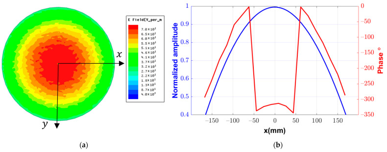
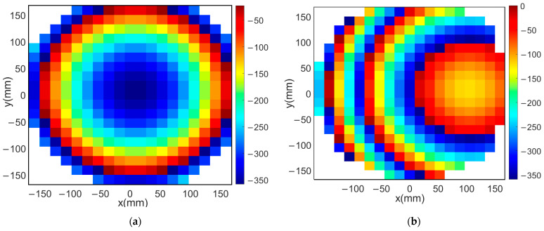
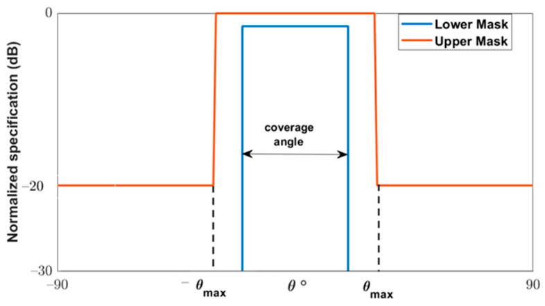
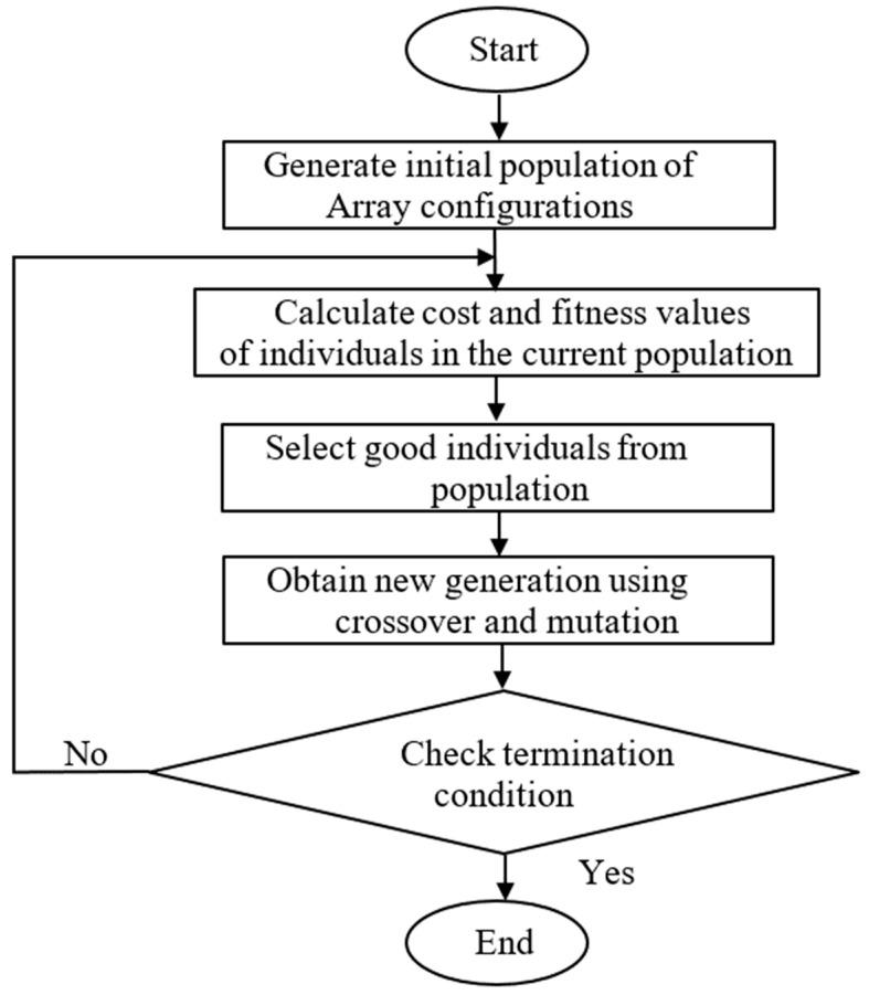
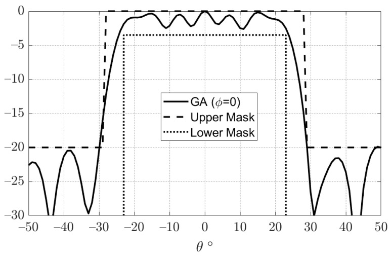
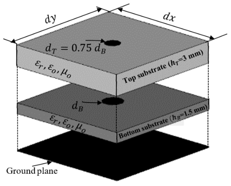
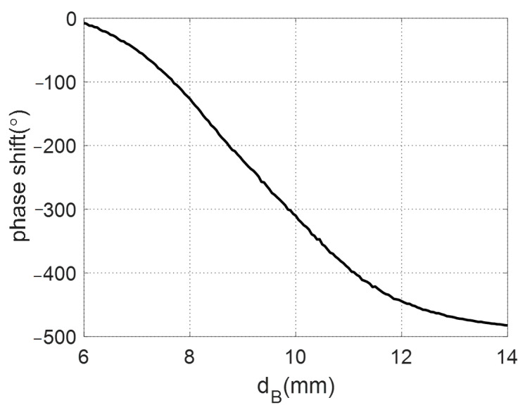
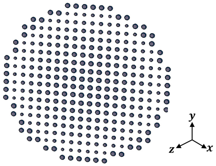
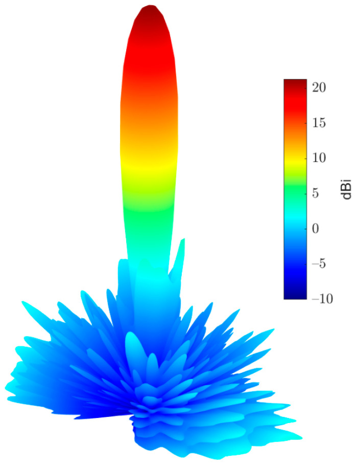
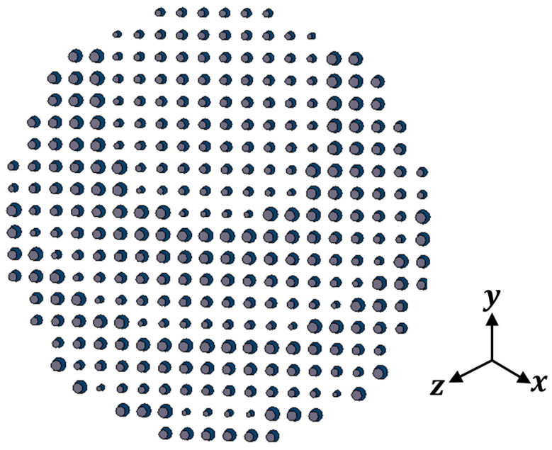
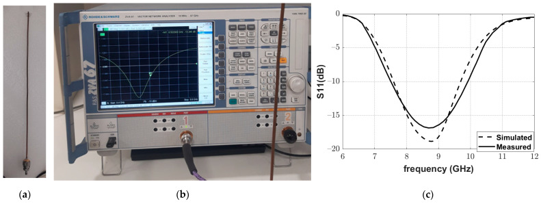
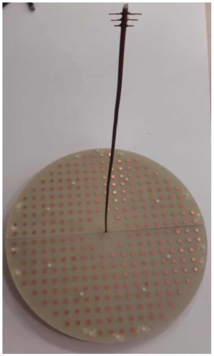
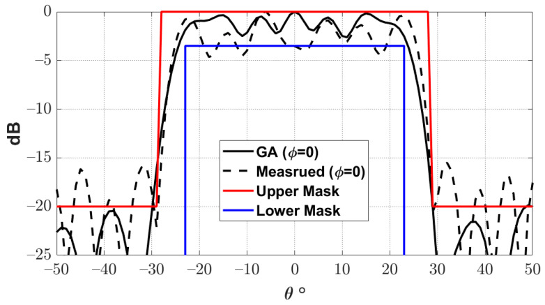
This paper presents the analysis and design of an X-band reflectarray. The proposed antenna can be used for a medium Earth orbit (MEO) remote sensing satellite system in the 8.5 GHz band. To obtain a nearly constant response along the coverage area of this satellite system, the proposed antenna was designed with a flat-top radiation pattern with a beam width of around 29° for the required MEO system. In addition, broadside pencil beam and tilted pencil beam reflectarrays were also investigated. The feeding element of the proposed reflectarray antennas is a Yagi-Uda array. The amplitude and phase distribution of the fields due to the feeding element on the aperture of the reflectarray antenna are obtained directly by numerical simulation without introducing any approximation. The required phase distribution along the aperture of the reflectarray to obtain the required flat-top radiation pattern is obtained using the genetic algorithm (GA) optimization method. The reflecting elements of the reflectarray are composed of stacked circular patches. This stacked configuration was found to be appropriate for obtaining a wide range of reflection phase shift, which is required to implement the required phase distribution on the reflectarray aperture. The antenna was fabricated and measured for verification.
Keywords: flat-top radiation pattern; genetic algorithm; reflectarray antenna; remote sensing satellite system.
Conflict of interest statement
The authors declare no conflict of interest.
Figures


Similar articles
-
Design and Analysis of Wideband Single-Layer Reflectarray Antenna for Remote Sensing and Environmental Monitoring.Sensors (Basel). 2025 Feb 5;25(3):954. doi: 10.3390/s25030954. Sensors (Basel). 2025. PMID: 39943593 Free PMC article.
-
Reflectarray antennas: a smart solution for new generation satellite mega-constellations in space communications.Sci Rep. 2020 Dec 9;10(1):21554. doi: 10.1038/s41598-020-78501-0. Sci Rep. 2020. PMID: 33299082 Free PMC article.
-
Exploring the Beam Squint Effects on Reflectarray Performance: A Comprehensive Analysis of the Specular and Scattered Reflection of the Unit Cell.Sensors (Basel). 2024 Feb 23;24(5):1438. doi: 10.3390/s24051438. Sensors (Basel). 2024. PMID: 38474976 Free PMC article.
-
Design and Validation of a Reflectarray Antenna with Optimized Beam for Ground Target Monitoring with a DVB-S-Based Passive Radar.Sensors (Basel). 2021 Aug 4;21(16):5263. doi: 10.3390/s21165263. Sensors (Basel). 2021. PMID: 34450720 Free PMC article.
-
Single-Layer Metasurface-Based Reflectarray Antenna with H-Shaped Slotted Patch for X-Band Communication.Nanomaterials (Basel). 2024 Sep 14;14(18):1495. doi: 10.3390/nano14181495. Nanomaterials (Basel). 2024. PMID: 39330652 Free PMC article.
Cited by
-
The Design of a Circularly Polarized Antenna Array with Flat-Top Beam for an Electronic Toll Collection System.Sensors (Basel). 2023 Nov 24;23(23):9388. doi: 10.3390/s23239388. Sensors (Basel). 2023. PMID: 38067761 Free PMC article.
References
-
- Rahmat-Samii Y., Densmore A.C. Technology trends and challenges of antennas for satellite communication systems. IEEE Trans. Antennas Propag. 2014;63:1191–1204. doi: 10.1109/TAP.2014.2366784. - DOI
-
- Prado D.R., Arrebola M., Pino M.R. Advances in Array Optimization. IntechOpen; London, UK: 2019. Reflectarray pattern optimization for advanced wireless communications.
-
- Dahri M.H., Jamaluddin M.H., Seman F.C., Abbasi M.I., Ashyap A.Y.I., Kamarudin M.R., Hayat O. A Novel Asymmetric Patch Reflectarray Antenna with Ground Ring Slots for 5G Communication Systems. Electronics. 2020;9:1450. doi: 10.3390/electronics9091450. - DOI
LinkOut - more resources
Full Text Sources
