Review
. 2022 Feb 18;17(15):1205-1226.
doi: 10.4244/EIJ-D-21-00582.

Echocardiographic guidance in transcatheter structural cardiac interventions

Affiliations
Review

Echocardiographic guidance in transcatheter structural cardiac interventions

Eustachio Agricola et al. EuroIntervention. .

Abstract

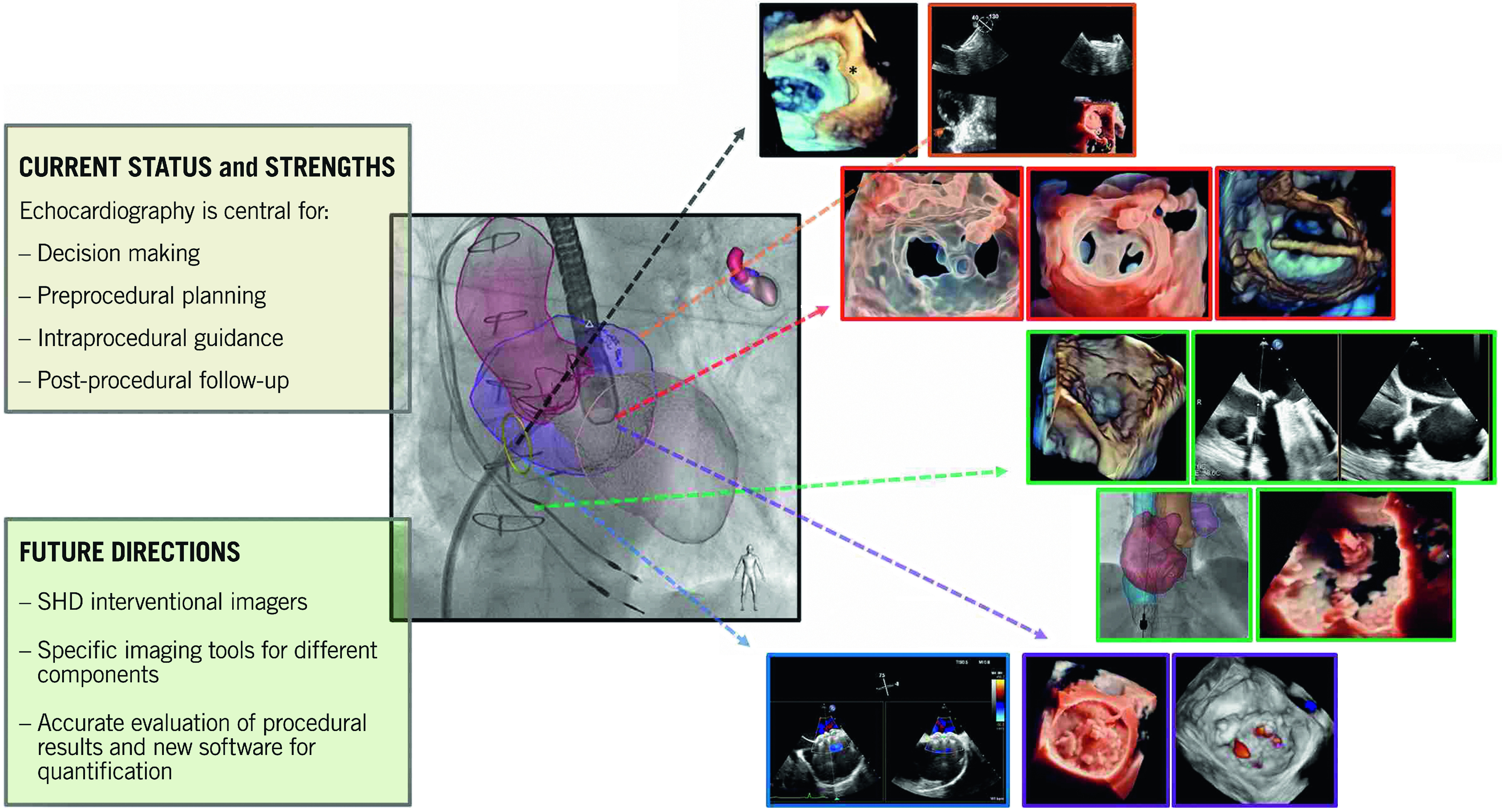
Catheter-based treatment of structural heart diseases (SHD) has seen tremendous advances in the past decades, thanks to the development of new devices and advances in imaging techniques. Today, we have an extensive armamentarium of imaging tools for preprocedural planning, intraprocedural guidance and follow-up of SHD. Intraprocedural guidance is based mainly on transoesophageal echocardiography; however, other imaging modalities are used as complementary or alternative techniques, each of them with its strengths and weaknesses. Thus, a multimodality imaging approach provides added values in this setting. As the field of imaging parallels the continuous technical improvements, this review will describe the state of the art imaging techniques, focusing on echocardiography during procedural guidance of the most common catheter-based interventions, providing tips and tricks for interventional cardiologists: in particular, how to guide transseptal crossing; left atrial appendage closure; transcatheter mitral or tricuspid valve repair or replacement; percutaneous closure of patent foramen ovale and atrial defects; and percutaneous closure of paravalvular leaks. Open challenges for the near future are the need for physicians with specific technical skills and competencies in SHD imaging, more attention to high levels of radiation exposure, and optimisation of intraprocedural and post-procedural evaluation.


Conflict of interest statement

The authors have no conflicts of interest to declare.

Figures

Figure 1
Figure 1. History and evolution of SHD intervention and interventional imaging.
ASD: atrial septal defect; CT: computed tomography; HOCM: hypertrophic obstructive cardiomyopathy; ICE: intracardiac echocardiography; LAA: left atrial appendage; PDA: patent ductus arteriosus; PFO: patent foramen ovalis; PMBV: percutaneous mitral balloon valvuloplasty; PTSMA: percutaneous transluminal septal myocardial ablation; PVL: paravalvular leak; RT: real time; SHD: structural heart disease; TAVR: transcatheter aortic valve replacement; TMVR: transcatheter mitral valve replacement; TOE: transoesophageal echocardiography; TSP: transseptal puncture; TTE: transthoracic echocardiography; VSD: ventricular septal defect.
Central illustration
Central illustration. Echocardiographic guidance for transcatheter structural cardiac interventions.
Figure 2
Figure 2. Recommended imaging modalities to display IAS
A) Anteroposterior projection: the IAS is displayed in an oblique perspective corresponding to the 3D oblique perspective from right atrium (H). B) Right anterior oblique projection: the IAS is displayed in en face perspective, corresponding to the 3D en face view from the right atrium (I). C) Left anterior oblique projection: the side-on profile of the IAS corresponding to either the 3D lateral perspective (J) or 2D bicaval view (90-120°) (D). D) Superior-inferior orientation. E) Short-axis (SAX) view at the base (30-50°) for anterior-posterior orientation. F) Biplane view that displays both the bicaval and the SAX view simultaneously. G) Four-chamber view (0°) to determine the height above the mitral valve.
Figure 3
Figure 3. Procedural steps of TSP.
A - C) Anteroposterior fluoroscopic projection showing the progressive steps of the TSP. A) Guidewire in the SVC. B) The catheter and needle in the FO and then the septum is punctured. C) The septum is crossed and the needle is removed. D) 2D TOE mid-oesophageal bicaval view showing the catheter tip coursing from the SVC to the FO. E- H) Sequential 2D TOE views showing the “tenting” of the catheter against the FO. I) 3DE overhead view showing the septum and the tenting (asterisk) in lateral perspective. J) Septal crossing confirmed by the transient appearance of bubbles in the LA. K) Catheter in the LA. 3DE: three-dimensional echocardiography; Ao: aorta; FO: fossa ovalis; IVC: inferior vena cava; LA: left atrium; MV: mitral valve; RA: right atrium; SVC: superior vena cava; TOE: transoesophageal echocardiography.
Figure 4
Figure 4. Fusion imaging guidance of TSP.
A) Patient-tailored anteroposterior (AP) fluoroscopic view “fused” with a 2D bicaval view of the IAS, showing the dilator coursing from the SVC to the FO. B) AP fluoroscopic view “fused” with a 3D en face view of the IAS from the RA, showing the fine position of the catheter tip into the FO. C) 3D lateral perspective of the IAS superimposed on an AP fluoroscopic projection showing the tenting (*). D) 3D oblique perspective of the IAS superimposed on an AP fluoroscopic view showing septal crossing. E) & F) Heart models obtained from 3D data sets and superimposed on the fluoroscopic view. The FO is identified by a yellow circle. Ao: aorta; AP: anterioposterior; FO: fossa ovalis; LA: left atrium; RA: right atrium; SVC: superior vena cava.
Figure 5
Figure 5. Recommended imaging modalities to evaluate the anatomy of the LAA.
A) 3D TOE transparency rendering. B) 3D CT volume rendering. C) CT coronal and sagittal (D) reconstructions. E – G) Set of 2D TOE views ranging from 0-to-135°. LAA: left atrial appendage; TOE: transoesophageal echocardiography
Figure 6
Figure 6. Recommended imaging modalities for LAA sizing.
The WATCHMAN device (Boston Scientific) size is chosen based on the dimensions of the LAA ostium (dotted line in TOE view) and the depth of the appendage. For the AMPLATZER Amulet device (Abbott Laboratories), the device landing zone is 1 cm distally from the LAA ostium (dashed line in TOE view). A) 3D TOE semi-automated measurement of LAA sizing based on MPR algorithm. LAA: left atrial appendage; MPR: multiplanar reconstruction; TOE: transoesophageal echocardiography
Figure 7
Figure 7. LAA closure procedural steps (AMPLATZER Amulet device).
A) Navigation inside the LAA with wire and catheter (3D overhead of the LAA). B) LAA engagement by the wire (3D en face view of LAA). C) Echocardiographic and angiographic LAA sizing. D) Implant projections: TOE views 0°-60°corresponding to RAO cranial view and 120°-135 corresponding to RAO caudal view. E) Lobe expansion. F) Disc opening. G) Tug test. H) Release and final result. I) Leak evaluation. CAU: caudal; CRA: cranial; LAA: left atrial appendage; RAO: right anterior oblique; TOE: transoesophageal echocardiography
Figure 8
Figure 8. LAA closure procedural steps.
A – C) Fusion imaging and D-E) ICE guidance. A) Heart model. Catheter inside the LAA. B & C) LAA is displayed in 3D rendering. B) Lobe expansion. C) Disc opening. D & E) ICE guidance during LAA occlusion. The ICE probe in the left atrium is showing the device on the delivery cable (D) and the device in its final position (E). ICE: intracardiac echocardiography; LAA: left atrial appendage
Figure 9
Figure 9. MitraClip procedural steps.
A) Baseline evaluation. B) Clip extrusion into the LA. C) Steering of the CDS towards the MV plane. D) Trajectory. E) Clip arm orientation. F) Clip advancement into the LV and leaflet grasping. G) Assessment of leaflet insertion. H) Clip release. I) 3D transparency rendering en face view of the MV showing the double orifice clearly. J) Final result. K) Transmitral gradient. L) Residual ASD evaluation. ASD: atrial septal defect; CDS: clip delivery system; LA: left atrium; LV: left ventricle; MV: mitral valve
Figure 10
Figure 10. PASCAL procedural steps.
A) Baseline evaluation. B) Parallelism test to ensure guide sheath tip flexes parallel to MV (3D en face view of the septum). C & D) implant system insertion: (C) implant elongated, and (D) implant closed. E) Steering towards the MV plane. F) Implant trajectory and positioning. G) Implant orientation. H) Identification of anterior and posterior clasp. I) Crossing valve. J) Leaflet capture. K) Implant closing. L) Transmitral gradient. M) Implant release. N) 3D transparency rendering en face view of MV showing the double orifice clearly. O) Post-implant release evaluation. MV: mitral valve
Figure 11
Figure 11. Fusion imaging with heart model in the MitraClip procedure - essential steps.
A) Navigation into the LA. B) Steering and positioning the DC towards the MV. C) The jet is displayed on the fluoroscopic screen and used as a reference marker (target lesion).
Figure 12
Figure 12. Cardioband procedure in the mitral valve.
A) Baseline evaluation. B) TSP: overhead perspective of the LA showing tenting with respect to the posteromedial commissure. C) System navigation around the target zone guided by 3D perspectives and LAO CAU fluoroscopic projection. D) Visualisation of the contact of IC with the annulus by biplane view and MPR. E) RAO projection used for implant and pull test. F) Size adjustment tool (SAT) insertion. G) 3D en face view of MV after SAT removal showing the implant as an incomplete surgical annuloplasty. H) LAO before cinching. I) After cinching. J) Final result. IC: implant catheter; LA: left atrium MPR: MV: mitral valve; TSP: transseptal puncture
Figure 13
Figure 13. Cardioband procedure in the tricuspid valve.
A) Baseline evaluation. B) Navigation of delivery system along the tricuspid annulus. C) 3D MPR for fine evaluation of the delivery catheter on the annulus. D) Right coronary angiography to assess injury of the RCA during anchor implantation. E) Final result. MPR: multiplanar reconstruction; RCA: right coronary artery
Figure 14
Figure 14. TriClip procedure.
A) Baseline evaluation. B) GC insertion into the RA. C) Steering manoeuvre towards the TV plane and trajectory (LAX transgastric view). D) CDS advancement into the RV (biplane transgastric views). E) Clip arm orientation (SAX transgastric view). F) Leaflet grasping. G) Residual TR after first clip implantation (SAX transgastric view). H) Assessment of leaflets insertion. I) Second clip implantation. J) Result after second clip. K) Transvalvular gradient. CDS: clip delivery system; GC: guide catheter; RA: right atrium; RV: right ventricle; SAX: short axis; TR: tricuspid regurgitation
Figure 15
Figure 15. TriClip procedure guided by ICE.
A) Baseline evaluation. B) Clip advancement into the RV. C) Leaflet grasping. D) Assessment of leaflet insertion. E) Final result. F) Transvalvular gradient. Courtesy of Mani Vannan, Marcus Heart Valve Center, Piedmont Heart Institute, Atlanta, USA. MV: mitral valve
Figure 16
Figure 16. Tricuspid PASCAL procedure.
A) Baseline evaluation. B) Guide sheath placement inside the RA. C) Implant system insertion. D) Trajectory. E) Clasp check. F) Implant orientation. G) Valve crossing. H) Confirmation of implant orientation. I) Implant retraction. J) Leaflet clasping. K) & L) Assessment of leaflet insertion. M) Result evaluation after implant release. Courtesy of Dr Ralph Stephan Von Bardeleben, Department of Cardiology I, Heart Valve Center, Universitätsmedizin Mainz, Mainz, Germany. RA: right atrium
Figure 17
Figure 17. ASD closure procedure.
A) Baseline evaluation and sizing of the defect. B) ASD crossing. C) & D) Balloon sizing. E) Left disc opening. F) Right disc opening and push-and-pull test. G) Device release. H) Colour-Doppler shows absence of residual shunt. ASD: atrial septal defect
Figure 18
Figure 18. ICE guidance of a double disc device PFO closure.
A) Long-axis atrial septal view at baseline. B) Left atrial disc opening. C) Approximation towards the IAS. D) The right disc opening. The device can be assessed in two planes (E & F) before the final release. After the final release (G), the bubble test should be repeated in order to assess the immediate result (H). IAS: interatrial septum; ICE: intracardiac echocardiography PFO: patent foramen ovale
Figure 19
Figure 19. Leak evaluation and preprocedural planning.
A & B) Localisation of mitral PVL. A) 3D colour-Doppler (transparency rendering). B) En face view of mitral valve prosthesis (3D true view rendering). C) Leak sizing by 3D MPR. D & E) Computed tomography (CT). D) Coronal view. E) Axial view of the prosthesis. CT evaluation is helpful particularly for sizing of the PVL and for deriving the working fluoroscopic projection. MPR: multiplanar reconstruction; PVL: paravalvular leak

References

    1. Rubio-Alvarez V, Limon R, Soni J. Valvulotomias intracardiacas por medio de un cateter [Intracardiac valvulotomy by means of a catheter]. [Article in Undertermined language]. Arch Inst Cardiol Mex. 1953;23:183–92. - PubMed
    1. Vignola PA, Swaye PS, Gosselin AJ. Safe transthoracic left ventricular puncture performed with echocardiographic guidance. Cathet Cardiovasc Diagn. 1980;6:317–24. - PubMed
    1. Hellenbrand WE, Fahey JT, McGowan FX, Weltin GG, Kleinman CS. Transesophageal echocardiographic guidance of transcatheter closure of atrial septal defect. Am J Cardiol. 1990;66:207–13. - PubMed
    1. Ballal RS, Mahan EF, Nanda NC, Dean LS. Utility of transesophageal echocardiography in interatrial septal puncture during percutaneous mitral balloon commissurotomy. Am J Cardiol. 1990;66:230–2. - PubMed
    1. Daoud EG, Kalbfletsch SJ, Hummel JD. Intracardiac echocardiography to guide transseptal left heart catheterization for radiofrequency catheter ablation. J Cardiovasc Electrophysiol. 1999;10:358–63. - PubMed

MeSH terms