. 2022 Feb;27(1):407-417.
doi: 10.1109/tmech.2021.3064954. Epub 2021 Mar 9.

MR-Tracked Deflectable Stylet for Gynecologic Brachytherapy

Affiliations

MR-Tracked Deflectable Stylet for Gynecologic Brachytherapy

Anthony L Gunderman et al. IEEE ASME Trans Mechatron. 2022 Feb.

Abstract

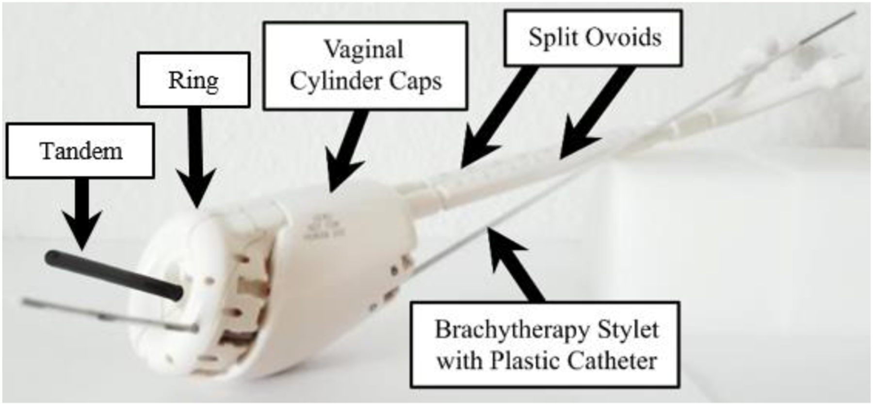
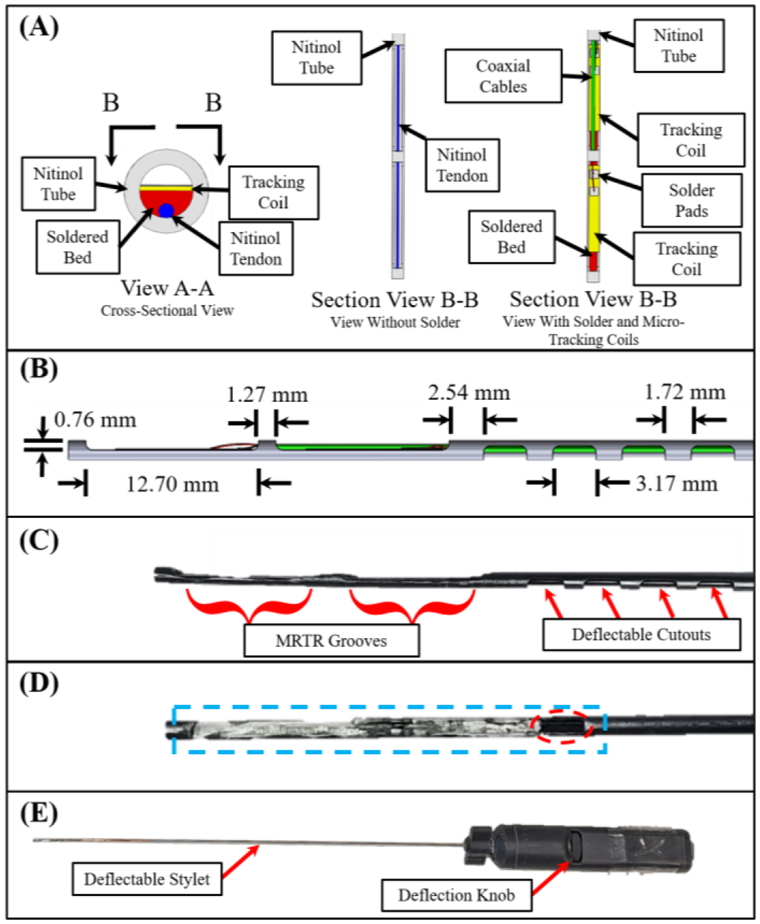
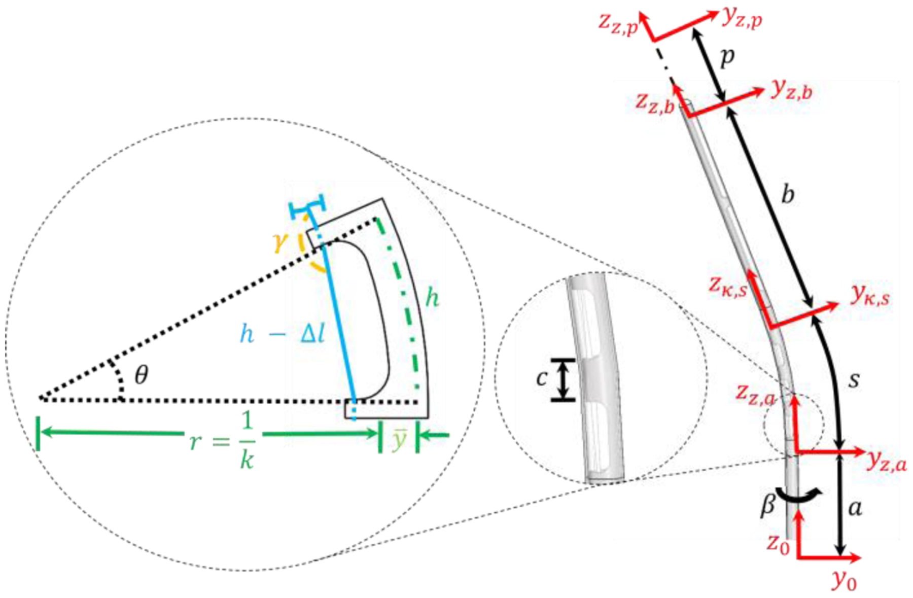
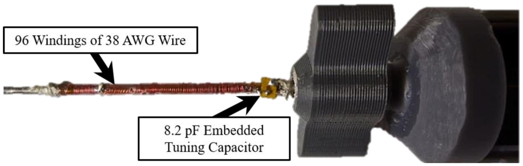
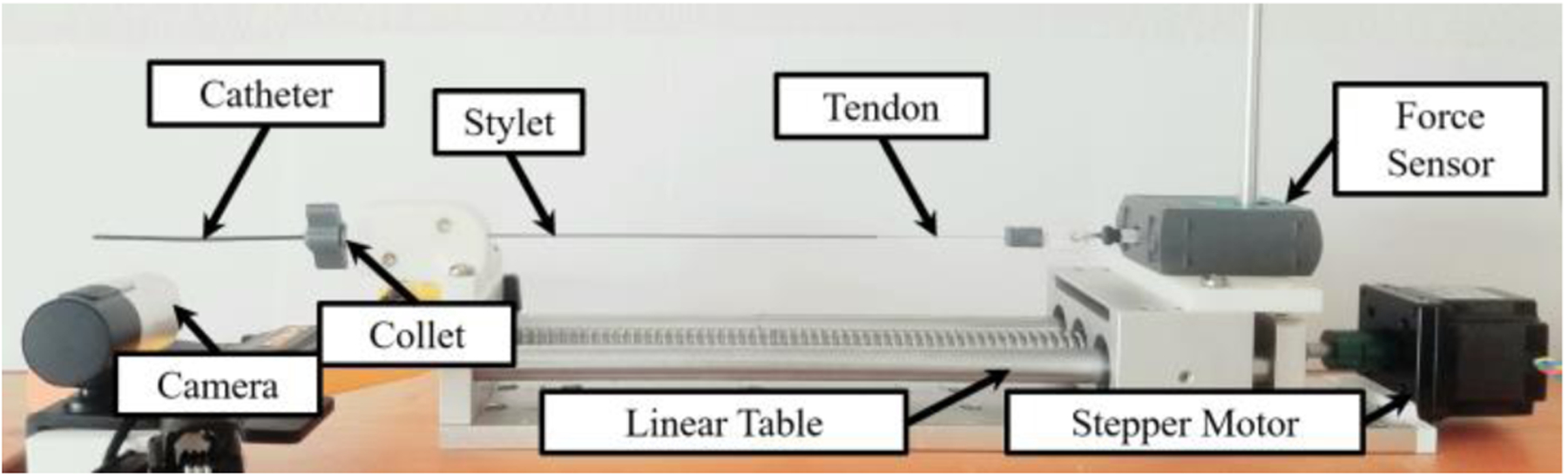
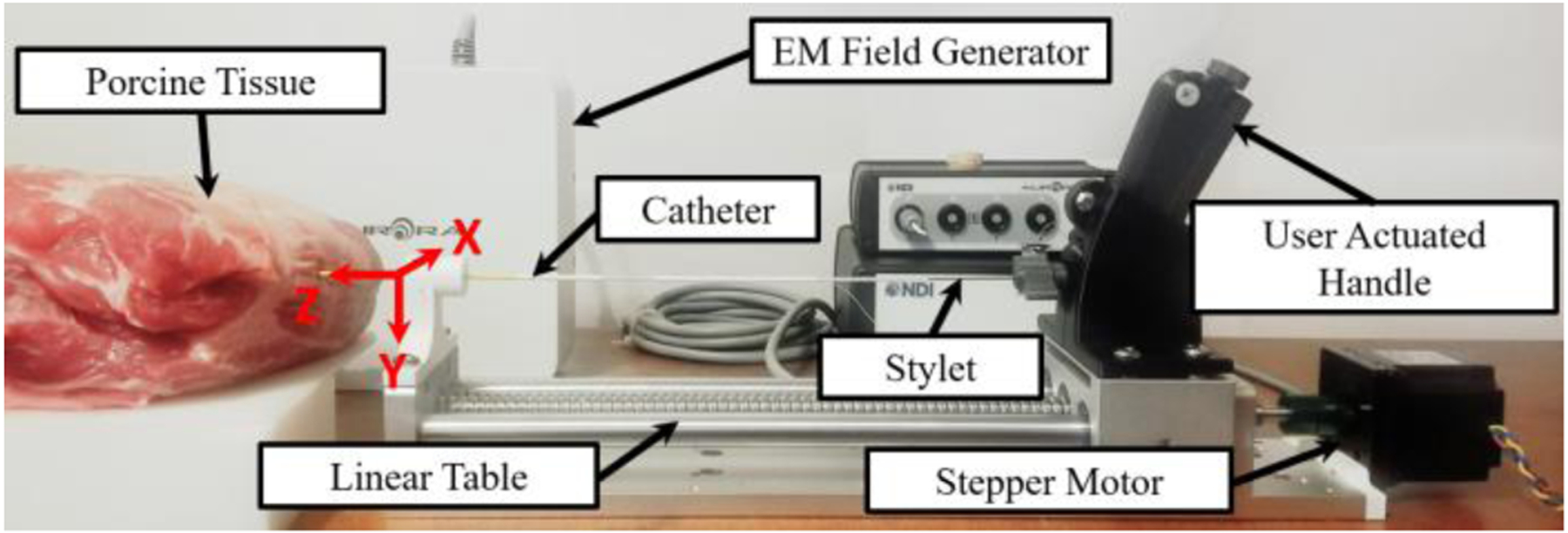
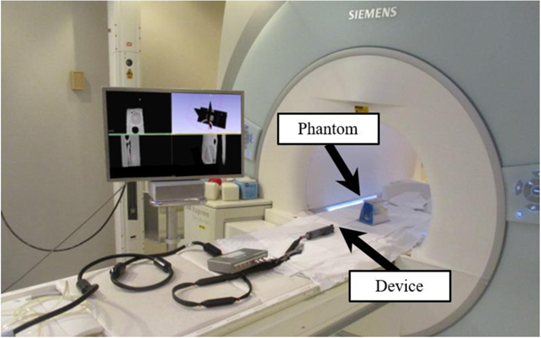
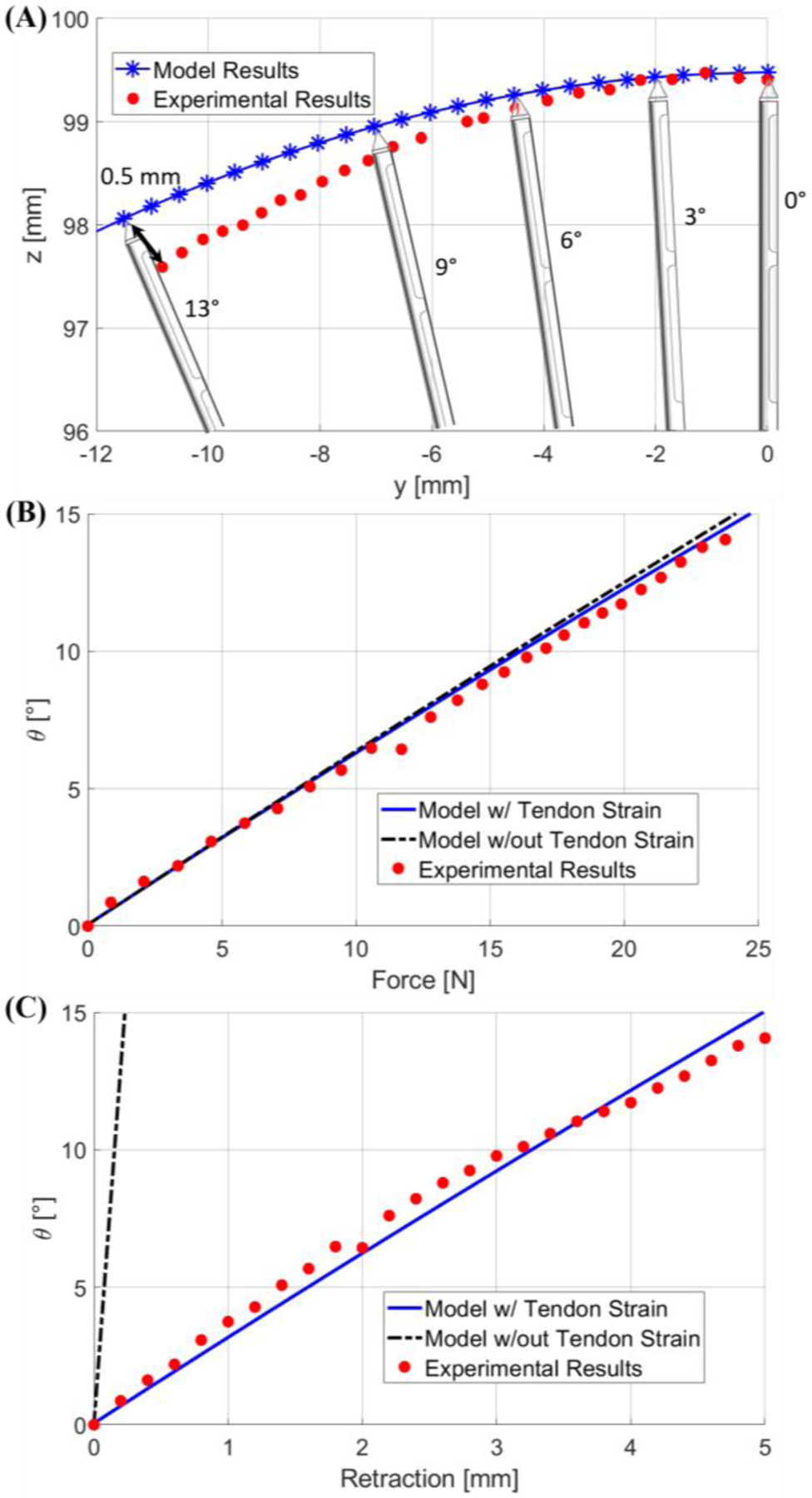
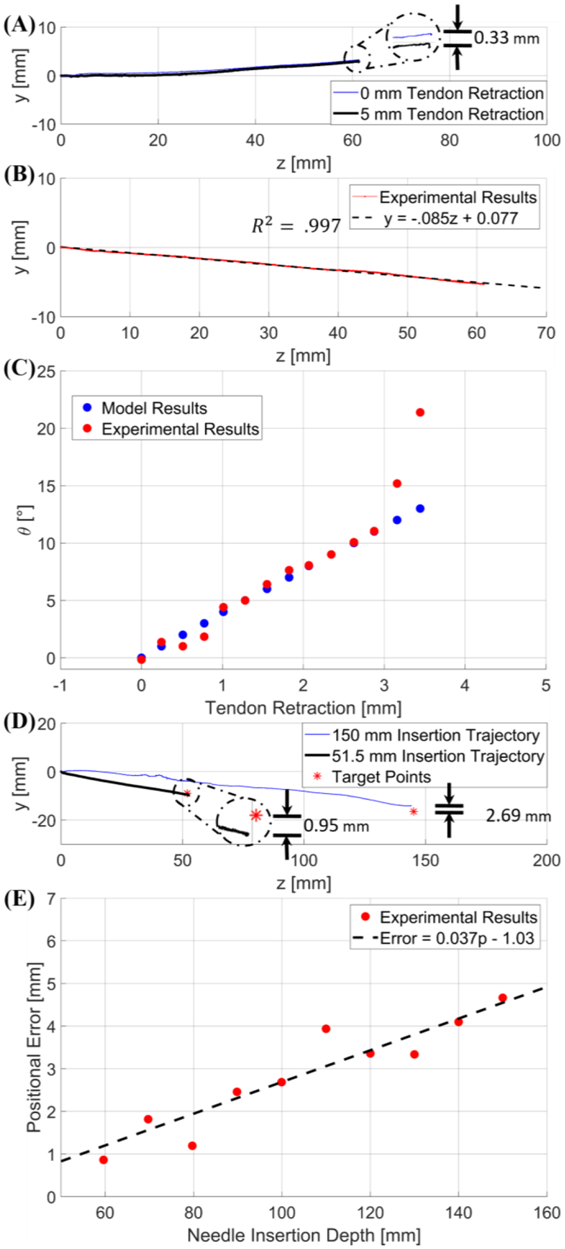
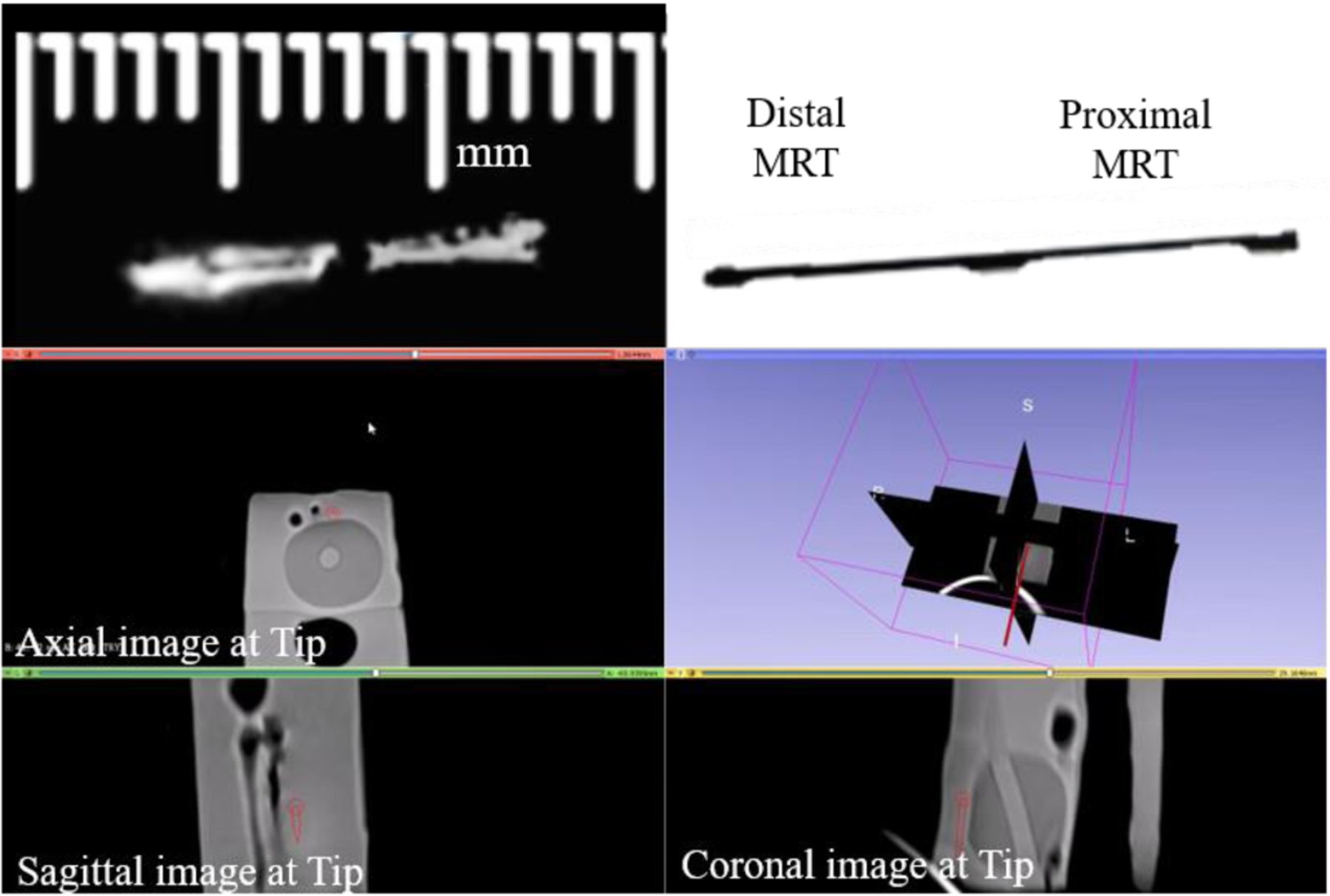
Brachytherapy is a radiation based treatment that is implemented by precisely placing focused radiation sources into tumors. In advanced interstitial cervical cancer bracytherapy treatment, this is performed by placing a metallic rod ("stylet") inside a hollow cylindrical tube ("catheter") and advancing the pair to the desired target. The stylet is removed once the target is reached, followed by the insertion of radiation sources into the catheter. However, manually advancing an initially straight stylet into the tumor with millimeter spatial accuracy has been a long-standing challenge, which requires multiple insertions and retractions, due to the unforeseen stylet deflection caused by the stiff muscle tissue that is traversed. In this paper, we develop a novel tendon-actuated deflectable stylet equipped with MR active-tracking coils that may enhance brachytherapy treatment outcomes by allowing accurate stylet trajectory control. Herein we present the design concept and fabrication method, followed by the kinematic and mechanics models of the deflectable stylet. The hardware and theoretical models are extensively validated via benchtop and MRI-guided characterization. At insertion depths of 60 mm, benchtop phantom targeting tests provided a targeting error of 1. 23 ± 0. 47 mm, and porcine tissue targeting tests provided a targeting error of 1. 65 ± 0. 64 mm, after only a single insertion. MR-guided experiments indicate that the stylet can be safely and accurately located within the MRI environment.

Keywords: Brachytherapy; Deflectable Stylet; MR tracking; Tendon-driven.


Figures

Fig. 1.
Fig. 1.
The Venezia gynecological applicator (Elekta, Sweden) depicts an interstitial catheter, which will be advanced through the cervix [10].
Fig. 2.
Fig. 2.
View A-A in (A) shows the solder bed (red), the nitinol tendon (blue), the MRTR coils (yellow), and the nitinol tube used as the brachytherapy stylet (grey). Section View B-B provides a downward looking view of the same assembly, without the solder (left), and with the solder, tracking coils, and micro-coaxial cables (right). (B) Side view of the stylet with the corresponding dimensions. (C) The stylet following the machining operations. (D) Stylet after machining the soldered surface flat (blue). Note the gap left to provide access for the micro-coaxial cables (dotted red ellipse). (E) Full handle assembly after assembly.
Fig. 3.
Fig. 3.
A single cutout being deflected and its corresponding geometry is depicted to the left based on tendon retraction. Blue is the tendon, the dashed green line is the location of the neutral bending plane, and the black dashed lines depict the change in the deflection angle. A side view (right) of the stylet is also given. The catheter surrounding the stylet is transparent. Additionally, the location of location coordinate frames can be seen in red.
Fig. 4.
Fig. 4.
The upper image is the proximal end of the handle assembly, which contains the tuning and matching circuits for the proximal and distal MR-Tracking coils. The lower images are the S11 plots of the distal and proximal MRT coils, as seen on a Vector Network Analyzer, after tuning and matching the circuitry. The resonance occurred at 63.8 MHz (the Larmor frequency of the Siemens 1.5T scanner).
Fig. 5.
Fig. 5.
An MBalun, which had a resonance frequency of 63.8 MHz, can be seen attached to the proximal end of the nitinol deflectable stylet.
Fig. 6.
Fig. 6.
Experimental setup for the force model validation test. Note that the background is white and the plastic catheter was darkened to work seamlessly with the MATLAB image processing techniques.
Fig. 7.
Fig. 7.
The experimental setup for the trajectory test in the porcine tissue is depicted above. The location and orientation of the robot base frame can be seen. The z-axis is in line with the stylet pointing toward the direction of insertion and the y-axis is orientated downwards. The stylet trajectory was obtained with an EM tracker.
Fig. 8.
Fig. 8.
Experimental setup inside Siemens 1.5T Espree MRI scanner for the MRI-guided navigational test, with deflectable stylet assembly and prostate phantom depicted in the MRI.
Fig. 9.
Fig. 9.
(A) is a plot of the stylet tip position when deflection angle increases from 0 to 13 degrees. (B) and (C) are plots of the stylet bending angle calculated by the two models with respect to force and tendon retraction, respectively. Note that previous model is indicated by the black hyphenated lines, whereas our model is indicated by the blue lines.
Fig. 10.
Fig. 10.
(A) is a graphical representation of the comparative study between a trajectory with 0 mm tendon retraction and a trajectory with 5 mm tendon retraction applied when the deflectable region is already inside the tissue. The error is depicted in the detailed view. (B) provides an example trajectory at a 5° user input, indicating a linear trajectory. (C) is a graph of the results from the second targeting test; blue represents the deflection angle vs. tendon retraction model per the modeling method in free space discussed in Section IV-A, and in red are the inclination angles of the experimental trajectories resulting from the corresponding tendon retraction. (D) provides two different trajectories within the porcine tissue with respect to their desired target locations (red asterisk). The 150 mm trajectory was obtained with initial deflection angle of 6.41° (blue line), and the 51.50 mm trajectory was obtained with initial deflection angle of 9.28° (black line). (E) is a graphical relationship between positional error and insertion depth within the porcine sample.
Fig. 11.
Fig. 11.
A side by side comparison can be seen of the tracking coils on the stylet scanned within a prostate phantom inside the MRI environment (left), next to an image of the stylet (right) obtained at the same configuration. The lower image is a 3D Slicer view depicting the instantaneous stylet tip location and orientation (dark red line) during navigation in a prostate phantom. The tip is linearly extrapolated from the locations determined from the MR-Tracking provided by the MRT coils.

References

    1. Sudhakar A, “History of Cancer, Ancient and Modern Treatment Methods,” Journal of cancer science & therapy, vol. 1, pp. 1–4, 2009. - PubMed
    1. Street W, “Cancer facts & figures 2019,” Am Cancer Soc, vol. 76, pp. 4, 2019. https://www.cancer.org/content/dam/cancerorg/research/cancer-facts-and-s....
    1. Halperin EC, Brady LW, Wazer DE, and Perez CA, Perez & Brady’s Principles and Practice of Radiation Oncology, 6th ed., Philadelphia: Lippincott Williams & Wilkins, 2013.
    1. Chargari C, Deutsch E, Blanchard P, Gouy S, Martelli H, Guerin F, Dumas I, Bossi A, Morice P, Viswanathan A, and Haie-Meder C, “Brachytherapy: An overview for clinicians,” Ca-a Cancer Journal For Clinicians, vol. 69, no. 5, pp. 386–401, SEP 2019, 2019. - PubMed
    1. Yamada Y, Rogers L, Demanes D, Morton G, Prestidges B, Pouliot J, Cohen G, Zaider M, Ghilezan M, and Hsu I, “American Brachytherapy Society consensus guidelines for high-dose-rate prostate brachytherapy,” Brachytherapy, vol. 11, no. 1, pp. 20–32, JAN-FEB 2012, 2012. - PubMed

LinkOut - more resources