. 2022 Feb 16;13(2):305.
doi: 10.3390/mi13020305.

Fibroblast Derived Skin Wound Healing Modeling on Chip under the Influence of Micro-Capillary Shear Stress

Affiliations

Fibroblast Derived Skin Wound Healing Modeling on Chip under the Influence of Micro-Capillary Shear Stress

Sharda Gupta et al. Micromachines (Basel). .

Abstract

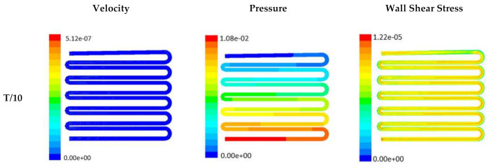
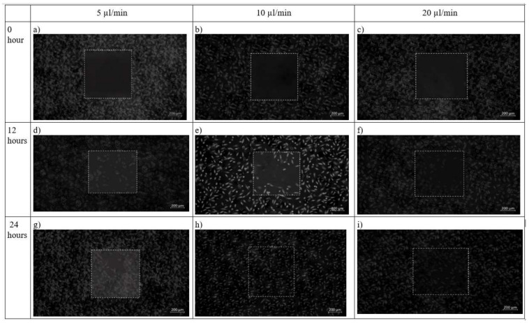
Fibroblast cell migration plays a crucial role in the wound-healing process. Hence, its quantitative investigation is important to understand the mechanism of the wound-healing process. The dynamic nature of the wound-healing process can be easily implemented using a microfluidic-based wound-healing assay. This work presented the use of a microfluidics device to simulate traumatic wounds on fibroblast cell monolayers by utilizing trypsin flow and PDMS barrier. In this study, a microfluidic chip with a transparent silk film is reported. The placement of film provides 3D cell culture conditions that mimic a 3D extracellular matrix (ECM) like environment and allows real-time monitoring of cells. A numerical study was conducted to evaluate the influence of dynamic medium-induced shear stress on the base and wall of the microchannel. This could facilitate the optimization of the inlet flow conditions of the media in the channel. At the same time, it could help in identifying stress spots in the channel. The scaffolds were placed in those spots for evaluating the influence of shear forces on the migratory behavior of fibroblast cells. The in vitro microfluidic assembly was then evaluated for cell migration under the influence of external shear forces during the wound-healing phenomena. A faster wound healing was obtained at the end of 24 h of the creation of the wound in the presence of optimal shear stress. On increasing the shear stress beyond a threshold limit, it dissociates fibroblast cells from the surface of the substrate, thereby decelerating the wound-healing process. The above phenomena were transformed in both coplanar microfluidics surfaces (by realizing in the multichannel interlinked model) and transitional microfluidics channels (by realizing in the sandwich model).

Keywords: fibroblast; microchannels; multilayered channels; sandwich model; shear stress; wound healing.


Conflict of interest statement

The authors declare no conflict of interest.

Figures

Figure 1
Figure 1
Schematic illustration of the two designs of microchannel of microfluidic chip used for the study; (a) design 1 with three inlet and outlet, (b) design 2 with one inlet and one outlet for fluid flow, (c) 3D view of design 1, (d) 3D view of complete chip of design 2. The media was injected through the inlet. In case of design 1, wound is made through flow of trypsin enzyme, whereas in design 2, the wound is created due to presence of PDMS barrier.
Figure 2
Figure 2
Schematic illustration of experimental procedure carried out. (a) Initially nonmulberry silk fibroin was added to PDMS mold to prepare transparent film. (b) Two chips were fabricated using laser micromachining.
Figure 3
Figure 3
Numerical simulation of fluid flow inside the chip design 1 at flow rate of 5 µL/min. The different time step was taken to understand the profile of velocity (a,d,g,j), pressure (b,e,h,k) and wall shear stress (c,f,i,l) along the channel.
Figure 4
Figure 4
Numerical simulation of fluid flow inside the chip design 1 at flow rate of 10 µL/min. The different time step was taken to understand the profile of velocity (a,d,g,j), pressure (b,e,h,k) and wall shear stress (c,f,i,l) along the channel.
Figure 5
Figure 5
Numerical simulation of fluid flow inside the chip design 1 at flow rate of 20 µL/min. The different time step was taken to understand the profile of velocity (a,d,g,j), pressure (b,e,h,k) and wall shear stress (c,f,i,l) along the channel.
Figure 6
Figure 6
Numerical simulation of fluid flow inside the chip design 2 at flow rate of 5 µL/min. The different time step was taken to understand the profile of velocity, pressure and wall shear stress along the channel.
Figure 6
Figure 6
Numerical simulation of fluid flow inside the chip design 2 at flow rate of 5 µL/min. The different time step was taken to understand the profile of velocity, pressure and wall shear stress along the channel.
Figure 7
Figure 7
Numerical simulation of fluid flow inside the design 2 at flow rate of 10 µL/min. The different time step was taken to understand the profile of velocity, pressure and wall shear stress along the channel.
Figure 7
Figure 7
Numerical simulation of fluid flow inside the design 2 at flow rate of 10 µL/min. The different time step was taken to understand the profile of velocity, pressure and wall shear stress along the channel.
Figure 8
Figure 8
Numerical simulation of fluid flow inside the design 2 at flow rate of 20 µL/min. The different time step was taken to understand the profile of velocity, pressure and wall shear stress along the channel.
Figure 8
Figure 8
Numerical simulation of fluid flow inside the design 2 at flow rate of 20 µL/min. The different time step was taken to understand the profile of velocity, pressure and wall shear stress along the channel.
Figure 9
Figure 9
FTIR spectra of the silk fibroin casted transparent film.
Figure 10
Figure 10
XRD spectra of the prepared silk fibroin film.
Figure 11
Figure 11
Micrographs of the wound-healing process of design 1 under a flow rate of 5 µL/min, 10 µL/min and 20 µL/min. Images are captured using bright field microscope (ZEISS Axio Vert.A1). Image analysis was performed using ImageJ software. Scale bar 200 µm.
Figure 12
Figure 12
Brightfield phase images of the fibroblast cells under design 2 at 0 h, 12 h and 24 h in the silk film placed inside slot in the microfluidic device. Micrographs of the wound-healing process of chip 2 under a flow rate of 5 µL/min (a,d,g), 10 µL/min (b,e,h) and 20 µL/min (c,f,i) taken using ZEISS Axio Vert.A1 inverted microscope. Image analysis was performed using ImageJ software. Scale bar 200 µm.
Figure 13
Figure 13
Result of MTT assay performed using L929 cell line. The fibroblast cell line was seeded on silk film and allowed to attach for 12 and 24 h of (a) Design 1, and (b) Design 2 migrating cells. The results are expressed as mean and error bars. The data was analyzed using One way ANOVA. Each experiment was performed in triplicate (* p < 0.05, ** p < 0.01, *** p < 0.005).

References

    1. Van Ravenzwaay B., Leibold E. A comparison between in vitro rat and human and in vivo rat skin absorption studies. Hum. Exp. Toxicol. 2004;23:421–430. doi: 10.1191/0960327104ht471oa. - DOI - PubMed
    1. Wufuer M., Lee G., Hur W., Jeon B., Kim B.J., Choi T.H., Lee S. Skin-on-a-chip model simulating inflammation, edema and drug-based treatment. Sci. Rep. 2016;6:37471. doi: 10.1038/srep37471. - DOI - PMC - PubMed
    1. Kimura H., Sakai Y., Fujii T. Organ/body-on-a-chip based on microfluidic technology for drug discovery. Drug Metab. Pharmacokinet. 2018;33:43–48. doi: 10.1016/j.dmpk.2017.11.003. - DOI - PubMed
    1. Bainbridge P. Wound healing and the role of fibroblasts. J. Wound Care. 2013;22:407–411. - PubMed
    1. Shen F., Li X., Li P.C. Study of flow behaviors on single-cell manipulation and shear stress reduction in microfluidic chips using computational fluid dynamics simulations. Biomicrofluidics. 2014;8:014109. doi: 10.1063/1.4866358. - DOI - PMC - PubMed

LinkOut - more resources