Review
. 2022 May;9(13):e2105146.
doi: 10.1002/advs.202105146. Epub 2022 Feb 25.

Biodegradable Elastomers and Gels for Elastic Electronics

Affiliations
Review

Biodegradable Elastomers and Gels for Elastic Electronics

Shuo Chen et al. Adv Sci (Weinh). 2022 May.

Abstract

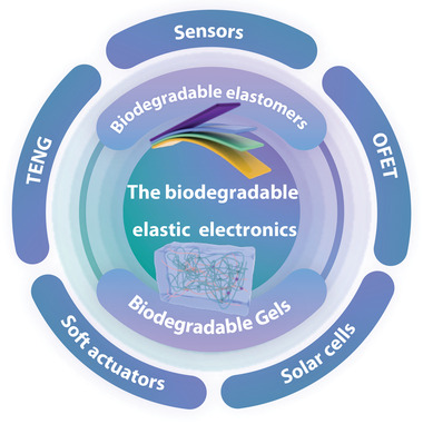
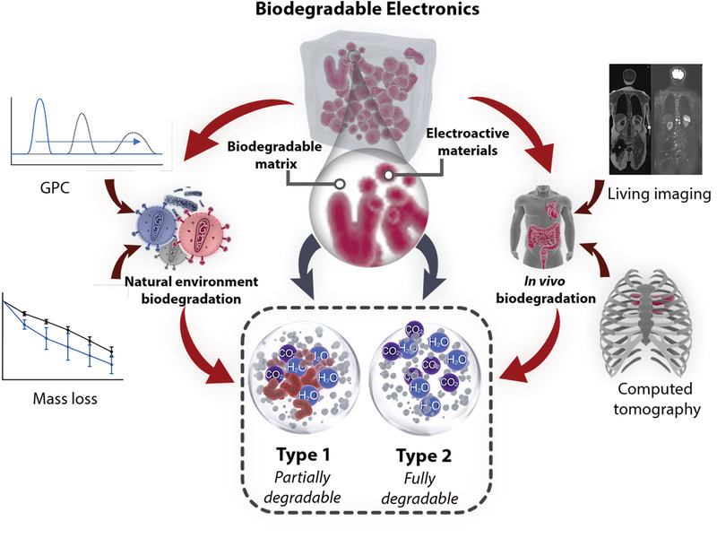
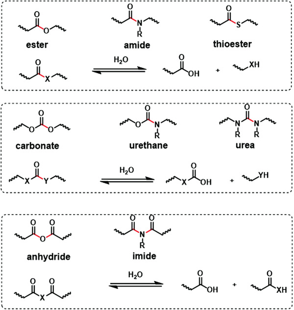
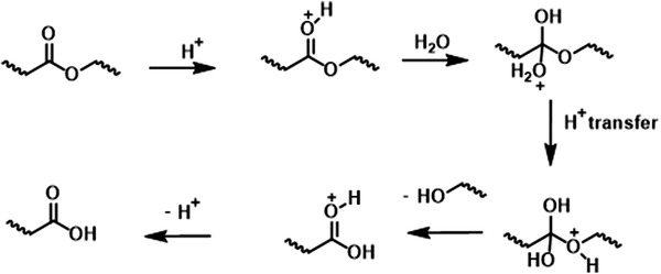
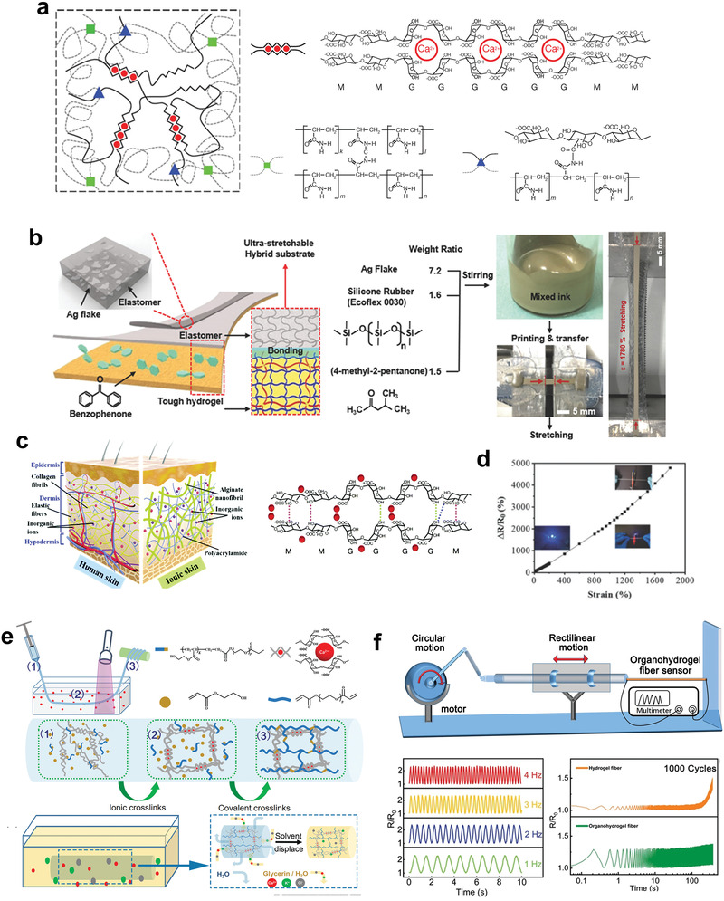
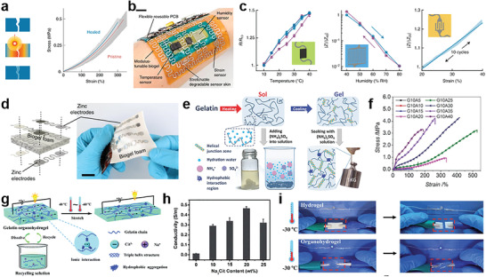
Biodegradable electronics are considered as an important bio-friendly solution for electronic waste (e-waste) management, sustainable development, and emerging implantable devices. Elastic electronics with higher imitative mechanical characteristics of human tissues, have become crucial for human-related applications. The convergence of biodegradability and elasticity has emerged a new paradigm of next-generation electronics especially for wearable and implantable electronics. The corresponding biodegradable elastic materials are recognized as a key to drive this field toward the practical applications. The review first clarifies the relevant concepts including biodegradable and elastic electronics along with their general design principles. Subsequently, the crucial mechanisms of the degradation in polymeric materials are discussed in depth. The diverse types of biodegradable elastomers and gels for electronics are then summarized. Their molecular design, modification, processing, and device fabrication especially the structure-properties relationship as well as recent advanced are reviewed in detail. Finally, the current challenges and the future directions are proposed. The critical insights of biodegradability and elastic characteristics in the elastomers and gel allows them to be tailored and designed more effectively for electronic applications.

Keywords: bio-friendly; biodegradable; elastic electronics; elastomers; gels; implantable electronics; wearable electronics.


Conflict of interest statement

The authors declare no conflict of interest.

Figures

Figure 1
Figure 1
Schematic illustration of the most commonly used biodegradable elastic electronics based on elastomers and gels.
Figure 2
Figure 2
Schematic illustration of biodegradable electronics and their characterization methods.
Figure 3
Figure 3
The hydrolyzable groups containing C═O bonds and the possible chemistry reactions. The hydrolyzable bonds are marked with red color. Reproduced with permission.[ 30 ] Copyright 2008, Elsevier.
Figure 4
Figure 4
The mechanism for acid‐catalyzed ester bonds hydrolysis, which is cleaved to yield carboxylic acid and alcohol. Reproduced with permission.[ 30 ] Copyright 2008, Elsevier.
Figure 5
Figure 5
Chemical structures of moieties susceptible to oxidative. The red stars represent the susceptible points. Reproduced with permission.[ 30 ] Copyright 2008, Elsevier.
Figure 6
Figure 6
Schematic illustration of elastic electronics, exhibiting their common fabrication strategies and required mechanical properties.
Figure 7
Figure 7
The chemical structure and application of PGS elastomers in electronics. a) Chemical structure of PGS, with emphasis on the susceptible sites (red stars) for biodegradability. b) The degradation of the device made from PGS, inside a solution of 0.5 m NaOH. Reproduced with permission.[ 81 ] Copyright 2014, Wiley‐VCH. c) Evolution of the piezoresistive response after 1 200 000 cycles. d) Electromechanical shaker displacement and the change of resistance reported at 300 Hz. Reproduced with permission.[ 82 ] Copyright 2019, Wiley‐VCH. e) Schematic illustration of fabrication procedure for flexible, hybrid, and biodegradable electrodes containing cross‐aligned Ag nanowires (Ag NWs) impregnated in PGS film. Reproduced with permission.[ 85 ] Copyright 2020, Wiley‐VCH. f) SEM images of the microstructured PGS films(left). The image of PGS biodegradable elastomer film (right). g) The average sensitivity and standard deviation over all the 20 sensors with an array of 4 × 5 elements. Reproduced with permission.[ 86 ] Copyright 2015, Wiley‐VCH. h) Materials and overall assembly of the fully biodegradable strain and pressure sensor. Reproduced with permission.[ 87 ] Copyright 2018, Springer Nature.
Figure 8
Figure 8
The modification and 3D printing of PGS elastomers for electronic applications. a). Synthesis scheme of PGSA from PGS. b) Stress–strain curves for biodegradable substrate candidates and an Ecoflex reference in cyclic linear tensile test (left). Embedded serpentine Galinstan interconnects in gelatin and PGSA‐19 for cyclic tensile tests (right). Reproduced with permission.[ 91 ] Copyright 2021, Wiley‐VCH. c) Schematic diagram of the fabrication of the 3D printing TENGs (3DP‐TENGs) and the hierarchical porous structure. d) The durability test of 3DP‐TENGs. Reproduced with permission.[ 92 ] Copyright 2018, Wiley‐VCH. e) The schematic illustration of the skin‐like PSeD‐U elastomers with physical and covalent hybrid cross‐linked structures. f) Typical tensile stress–strain curves of PSeD‐U‐12h elastomers with different densities of hydrogen bond while practically identical covalent cross‐linking densities. g) Pressure–response curve of the piezocapacitive pressure sensor. Reproduced with permission.[ 106 ] Copyright 2020, Springer Nature.
Figure 9
Figure 9
The POC elastomers used in electronics. a) Chemical structure of PGS, with emphasis on the susceptible sites (red stars) for biodegradability. b) Images at various stages of dissolution of a device during immersion in PBS. Reproduced with permission.[ 109 ] Copyright 2015, American Chemical Society. c) Schematic diagram of chemical structures of POMAC with different synthesis path. d) Materials and overall assembly of the fully biodegradable strain and pressure sensor (top). Picture of the assembled sensor (bottom). Reproduced with permission.[ 111 ] Copyright 2018, Springer Nature.
Figure 10
Figure 10
The biodegradable polyurethane elastomers. a) Schematic of the synthesis and structure of PSeHCD elastomers with both extensive evenly distributed H‐bonds physical cross‐linking and controlled partially chemical cross‐linking. The degradable sites were marked with red stars. b) Self‐healing and reprocessing of PSeHCD elastomers. Stress–strain curves of original and self‐healed PSeHCD‐60 strips. c) Optical images of the healed PSeHCD‐60 strip before and after stretching. d) Microscopic images of self‐healing procedure of a scratch on the surface of a PSeHCD‐60 film. e) The application of strain sensor based on PSeHCD‐60 and PEDOT:PSS. Reproduced with permission.[ 116 ] Copyright 2021, Oxford University Press.
Figure 11
Figure 11
The dynamically covalent cross‐linked elastomers. a) Molecular structure of the PFB with dynamic covalent bond by DA reaction. The degradable sites were marked with green blanks. b) The 3D printing of the PFB elastomer. c) The recycle of electronics based on PFB elastomers. From top to bottom: TENG, pressure sensor, and flexible keyboard (right) and the corresponding electrical performance (left). Reproduced with permission.[ 120 ] Copyright 2020, Wiley‐VCH.
Figure 12
Figure 12
The biodegradable elastic conductors and semiconductors. a) Schematic synthesis of PGSAP prepolymer and cross‐linking with HDI to obtain PGSAP‐H polymers. b) Stress–strain behavior of PGSAP‐H polymer films. c) The conductivity of PGSAP‐H polyurethane films. Reproduced with permission.[ 62 ] Copyright 2016, Elsevier. d) Synthetic scheme of the DCPU. e) Biodegradable DCPU film and its high elasticity presented by stretching and recoiling. f) Dependence of electrical conductivity of DCPU‐0.3/1 on applied strains. Reproduced with permission.[ 124 ] Copyright 2016, Springer Nature. g) Chemical structure of the biodegradable elastomer (E‐PCL) based on polycaprolactone and the known degradation pathway of PCL (upper). Chemical structure of the fully degradable semiconducting polymer, p(DPP–PPD), and the monomeric byproducts after initial cleavage (bottom). h) The change in saturation mobility of neat and nanoconfined p(DPP–PPD) during stretching to 100% strain with both parallel (left) and perpendicular (right) to the charge transport direction. Reproduced with permission.[ 61 ] Copyright 2019, American Chemical Society.
Figure 13
Figure 13
The alginate‐based gels. a) Schematic diagram of the alginate–polyacrylamide hybrid gel with double networks. Reproduced with permission.[ 139 ] Copyright 2012, Springer Nature. b) The fabrication and photographs of the stretchable conductor containing the hybrid substrate and conductive ink layer. Reproduced with permission.[ 140 ] Copyright 2018, Wiley‐VCH. c) Design and synthesis of high‐performance sodium alginate (SA)/NaCl/PAAm ionic double network hydrogels. d) Relative resistance changes of the sensors on applied tension. The inset pictures are the luminance variations of LEDs with the increase of tensile and compression loading. Reproduced with permission.[ 150 ] Copyright 2019, Royal Society of Chemistry. e) Design and fabrication of organohydrogel fibers. f) The application of organohydrogel fiber as a sensor for high‐frequency and high‐speed motion. Reproduced with permission.[ 155 ] Copyright 2020, Wiley‐VCH.
Figure 14
Figure 14
The gelatin‐based gels. a) Schematic of the laser healing process (left) and the corresponding stress–strain curves of pristine and cut‐and‐healed gel samples (right). b) Soft e‐skin on a human arm. Scale bar = 3 cm. c) Characterization of the temperature sensors (left), humidity (middle), and strain sensors (right) of the soft e‐skins. d) Schematic illustration of orientation and design of zinc electrodes and the degradable stretchable pressure sensor array based on biogel foam. Scale bar = 2 cm. Reproduced with permission.[ 162 ] Copyright 2020, Springer Nature. e) Strengthening mechanisms of gelatin–ammonium sulfate hydrogels. f) Tensile stress–strain curves of the gelatin hydrogels with different (NH4)2SO4 concentrations. Reproduced with permission.[ 173 ] Copyright 2017, Wiley‐VCH. g) Schematic illustration of the structure and versatility of the fully recyclable gelatin organohydrogel. h) The influence of Na3Cit amounts to the conductivity of the organohydrogels. i) The conductivity and mechanical robustness of the hydrogel and organohydrogel after freezing at 30 °C for 24 h. Reproduced with permission.[ 176 ] Copyright 2020, Royal Society of Chemistry.

References

    1. Kim D.‐H., Lu N., Ma R., Kim Y.‐S., Kim R.‐H., Wang S., Wu J., Won S. M., Tao H., Islam A., Yu K. J., Kim T.‐i., Chowdhury R., Ying M., Xu L., Li M., Chung H.‐J., Keum H., McCormick M., Liu P., Zhang Y.‐W., Omenetto F. G., Huang Y., Coleman T., Rogers J. A., Science 2011, 333, 838. - PubMed
    1. Hammock M. L., Chortos A., Tee B. C.‐K., Tok J. B.‐H., Bao Z., Adv. Mater. 2013, 25, 5997. - PubMed
    1. Kaltenbrunner M., Sekitani T., Reeder J., Yokota T., Kuribara K., Tokuhara T., Drack M., Schwödiauer R., Graz I., Bauer‐Gogonea S., Bauer S., Someya T., Nature 2013, 499, 458. - PubMed
    1. Wang W., Yu A., Zhai J., Wang Z., Adv. Fiber Mater. 2021, 3, 394.
    1. Meng W., Nie M., Liu Z., Zhou J., Adv. Fiber Mater. 2021, 3, 149.

Publication types

LinkOut - more resources