Review
. 2022 Feb 10;23(4):1981.
doi: 10.3390/ijms23041981.

Microfluidic-Based Technologies for CTC Isolation: A Review of 10 Years of Intense Efforts towards Liquid Biopsy

Affiliations
Review

Microfluidic-Based Technologies for CTC Isolation: A Review of 10 Years of Intense Efforts towards Liquid Biopsy

Lucie Descamps et al. Int J Mol Sci. .

Abstract

The selection of circulating tumor cells (CTCs) directly from blood as a real-time liquid biopsy has received increasing attention over the past ten years, and further analysis of these cells may greatly aid in both research and clinical applications. CTC analysis could advance understandings of metastatic cascade, tumor evolution, and patient heterogeneity, as well as drug resistance. Until now, the rarity and heterogeneity of CTCs have been technical challenges to their wider use in clinical studies, but microfluidic-based isolation technologies have emerged as promising tools to address these limitations. This review provides a detailed overview of latest and leading microfluidic devices implemented for CTC isolation. In particular, this study details must-have device performances and highlights the tradeoff between recovery and purity. Finally, the review gives a report of CTC potential clinical applications that can be conducted after CTC isolation. Widespread microfluidic devices, which aim to support liquid-biopsy-based applications, will represent a paradigm shift for cancer clinical care in the near future.

Keywords: CTC isolation; circulating tumor cells; downstream analysis; liquid biopsy; microfluidic devices.


Conflict of interest statement

The authors declare no conflict of interest.

Figures

Figure 1
Figure 1
Emerging microfluidic technologies for CTC isolation. Data collected from Web of Science advanced search using specific keywords (“CTC”, “CellSearch”, “Microfluidic”, “Chip”).
Figure 2
Figure 2
CTC-enrichment technologies based on their physical properties through integrated microposts (microfiltration), specific microchannel designs (hydrodynamics), or application of electric fields (dielectrophoresis). CTCs appear in blue, while RBCs and WBCs are represented in red and pink, respectively. Created with BioRender.com (Accessed on 31 January 2022).
Figure 3
Figure 3
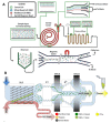
Microfiltration separation technologies. (A) Microfluidic ratchets for continuous CTC separation. Whole blood is infused from the bottom-left corner of the funnel array and cells travel in a zigzag diagonal path until they reach a blocking funnel row, where they proceed horizontally toward the outlet reservoirs. The size of funnel constrictions is gradually reduced from the bottom row to the top row within the 2D array. Reprinted from [29] with permission (http://creativecommons.org/licenses/by/4.0/) (Accessed on 26 October 2021). (B) Circular microcavity array (MCA) filter. The size of the microcavities was optimized in order to trap CTCs on the microcavities while letting blood cells flow through the filter. Reprinted with permission from [44]. Copyright 2010 American Chemical Society. (C) Pyramidal MCA filter. Top view and vertical section of cell retention in a pyramidal MCA. RT and RL are, respectively, the radius of the curvature of the trailing and leading edges of the cell. Reprinted from [34], copyright 2019, with permission from Elsevier. (D) The Parsortix™ system. Blood is forced along a series of channels with a cross-sectional gap that gradually decreases the dimension of the fluid path and retains CTCs based on their deformable nature and size. Reprinted with permission from [41] under the Creative Commons CC-BY-NC-ND license.
Figure 4
Figure 4
Hydrodynamic separation technologies. (A) Deterministic lateral displacement. An array of triangular posts with a gap distance of 42 µm was integrated into a microfluidic channel for continuous CTC sorting. CTCs constantly collide with posts and are forced to move laterally following the post arrangement. Reprinted with permission from [54] under a Creative Commons Attribution (CC BY) license. (B) Inertial focusing in a straight channel. The multi-flow configuration leads to the lateral migration of CTCs from the sample streams into the buffer stream due to the predominancy of the rotation-induced lift force (FΩ). Reprinted with permission from [58] (http://creativecommons.org/licenses/by/4.0/) (Accessed on 26 October2021). (C) Dean flow fractionation. CTCs move toward the inner wall of the spiral microchannel, because of the balance of inertial lift force and Dean drag force, while small cells (RBCs and WBCs) flow toward the outer wall. Reprinted with permission from [59] (http://creativecommons.org/licenses/by-nc-nd/3.0/) (Accessed on 26 October 2021). (D) Microvortices. Cells flowing through a series of expansion–contraction reservoirs experience multiple microvortices because of the shear gradient lift force in expansion reservoirs. CTCs are collected in the center of the vortices. Reprinted with permission from [60] (http://creativecommons.org/licenses/by/4.0/) (Accessed on 26 October 2021).
Figure 5
Figure 5
Dielectrophoretic separation technologies. (A) The ApoStream™ system. The flow chamber applies an AC electric field to the sample at a frequency in between the crossover frequency of CTCs and WBCs to pull the former towards the chamber floor (positive DEP) and repel the latter (negative DEP). Reprinted from [78] with the permission of AIP Publishing. (B) Wireless bipolar electrode (BPE) array. Capacitive charging of the electrical double layer at the BPE tips transmits an AC field across the device and provides sufficient electric field gradients to exert DEP trapping force. Cancer cells (in green) experience positive DEP and are trapped at the electric field maxima around the BPE tips (single-cell capture), while other cells (in yellow) undergo negative DEP and remain in fluid flow. Reprinted (adapted) with permission from [84]. Copyright 2017 American Chemical Society.
Figure 6
Figure 6
CTC-enrichment technologies based on their biological properties via antigen–antibody recognition through either surface functionalization or immunomagnetic separation using magnetic particles. Created with BioRender.com (Accessed on 31 January 2022).
Figure 7
Figure 7
Surface affinity-based separation technologies. (A) CTC-Chip. CTCs are trapped on micropillars functionalized with anti-EpCAM antibodies. Reprinted by permission from [93]. (B) NanoVelcro chip. Silicon nanopillars are coated with anti-EpCAM antibodies. This strategy takes advantage from the nano-roughened surface of the NP assemblies to increase contact between CTCs and immobilized antibodies. Reprinted with permission from [97]. (C) GO Chip. Graphene oxide nanosheets are adsorbed onto the gold pattern and functionalized with anti-EpCAM antibodies. Reprinted (adapted) by permission from [98]. (D) Tuned HBCTC-Chip for CTC release. (a) Thiol-functionalized gold nanoparticles (AuNPs). (b) Chip surface coating with AuNPs for CTC capture. In the presence of excess thiol molecules (GSH), the original thiol ligands with immobilized antibodies on the surface of the AuNPs can be exchanged with GSH molecules. Based on this thiol exchange reactions, captured CTCs can be detached from the chip surface, as represented in (b). Reprinted with permission from [99]. Copyright 2017 American Chemical Society.
Figure 8
Figure 8
Magnetic sources for CTC isolation from macroscale to microscale. (A,C) From the use of an external permanent magnet to the integration of nickel microstructures within the microfluidic channel. These microstructures, acting like microtraps, achieved an average 18.4% increase in capture rate of magnetically labeled CTCs in comparison with the previous design. Reprinted with permission from [109]. Reproduced from [110] (http://creativecommons.org/licenses/by/4.0/) (Accessed on 27 October 2021). (B,D) Toward the combination of X-shaped velocity valleys as low-flow velocity regions with circular nickel microstructures as capture spots. This configuration achieved a >90% capture efficiency for cancer cell lines with various EpCAM expression levels and enabled them to be magnetically ranked, thanks to the gradual increase in nickel microstructure size. The capture of low-expression cells requires the action of larger nickel structures; therefore, it occurs in the later zones of the chip. Reproduced from [111] with permission from the Royal Society of Chemistry. Reprinted from [112] by permission from Nature.
Figure 9
Figure 9
Ephesia technology for CTC isolation. (A) Self-assembly of anti-EpCAM functionalized magnetic beads along the microchannel height, which act as traps for CTCs. Columnar bead arrays were localized by microcontact printing of a magnetic pattern made of ferrofluid. Captured CTCs can be released by removing the external permanent magnet. Red letter B represents the magnetic field as a “magnetic field ON”. Reprinted with permission from [116]. Copyright 2010 American Chemical Society. (B) Arrangement of functionalized magnetic nanospheres within the microchannel through the use of a nickel patterns. The liquid-biopsy-guided drug release system (LBDR system) consists of two areas loaded with two types of functionalized magnetic nanospheres (MNs). Tumor cells are first recognized and captured by EpCAM-aptamer-functionalized MNs (Area I) which leads to the release of corresponding complementary strands (cDNAs), due to the conformational change of the aptamers. cDNAs present cleaving capability, which could trigger a subsequent doxorubicin (DOX) drug release process (Area II). Reproduced from [117] with permission from the Royal Society of Chemistry.
Figure 10
Figure 10
Heterogeneity tracking in immunomagnetic-based separation systems. (A) Spiral shape design can gradually decrease the distance to the center circular shape permanent magnet. Heterogeneous CTCs specifically position in trapping segments regarding the number of anti-EpCAM-conjugated magnetic nanoparticles on their surface. Low-expression cells will be captured in the center of the spiral channel where the distance to the external permanent magnet is small. Reprinted from [124], with permission from Elsevier. (B) Prismatic deflection separates a continuous CTC sample stream into discrete subpopulations based on CTC surface marker expression level. Co-based ferromagnetic guides are made up of distinct segments having angles ranging from 2 to 30° and, in the presence of an external magnetic field, induce a lateral deflection of a magnetically labeled target. The angle of the deflection guides relative to the direction of flow dictates the direction of the magnetic force, while the amount of magnetic loading on the surface of the cell dictates its magnitude. Reprinted with permission from [125]. Copyright 2018 American Chemical Society.
Figure 11
Figure 11
Tumor-marker-independent selection. (A) Two-stage microfluidic chip for negative selection of CTCs. (a) Magnetically labeled WBCs are first eliminated in the first immunomagnetic stage and (b) CTCs are then selectively isolated based on their surface marker expression in the anti-EpCAM-coated chip region. Reprinted from [119], with permission from Elsevier. (B) Whole workflow for high-throughput CTC separation from full (65 mL) leukapheresis samples. RBCs and platelets are first removed from leukapheresis products using size-based inertial separation, followed by immunomagnetic removal of WBCs, which were labeled prior with a mixture of biotinylated antibodies targeting the pan-leukocyte cell surface antigens. CTCs were recovered without relying on antigen markers. Reprinted with permission from [128] under the Creative Commons Attribution License 3.0.
Figure 12
Figure 12
Integrated separation devices combining a size-based pre-enrichment step and an immunomagnetic-based purification step. (A) Integration of inertial sorter and magnetic sorter modules. Complete RBCs removal and partial WBC depletion through an inertial separation step in a spiral-shaped microchannel, followed by immunomagnetic separation of magnetically labeled CTC. The labeling step of CTCs with anti-EpCAM-coated magnetic beads is performed on-chip. The magnetic sorting step enabled the distinct isolation of CTCs according to their EpCAM expression levels by adjusting the distance of the external magnet from magnetic particles flowing in the sorter. Reprinted with permission from [133] (https://creativecommons.org/licenses/by/4.0/) (Accessed on 27 October 2021). (B) CTC-iChip technology. RBCs and platelets are first removed by deterministic lateral displacement and remaining CTCs and magnetically labeled WBCs then enter two successive inertial focusing/magnetic sorting stages for WBC depletion. Reprinted with permission from [135] (https://creativecommons.org/licenses/by/4.0/) (Accessed on 27 October 2021).

Similar articles

Cited by

References

    1. Mehlen P., Puisieux A. Metastasis: A question of life or death. Nat. Rev. Cancer. 2006;6:449–458. doi: 10.1038/nrc1886. - DOI - PubMed
    1. Ashworth T.R. A Case of Cancer in Which Cells Similar to Those in the Tumours Were Seen in the Blood after Death. Med. J. Aust. 1869;14:146–147.
    1. Hölzel M., Bovier A., Tüting T. Plasticity of tumour and immune cells: A source of heterogeneity and a cause for therapy resistance? Nat. Rev. Cancer. 2013;13:365–376. doi: 10.1038/nrc3498. - DOI - PubMed
    1. Chemi F., Mohan S., Guevara T., Clipson A., Rothwell D.G., Dive C. Early Dissemination of Circulating Tumor Cells: Biological and Clinical Insights. Front. Oncol. 2021;11:672195. doi: 10.3389/fonc.2021.672195. - DOI - PMC - PubMed
    1. Lin E., Cao T., Nagrath S., King M.R. Circulating Tumor Cells: Diagnostic and Therapeutic Applications. Annu. Rev. Biomed. Eng. 2018;20:329–352. doi: 10.1146/annurev-bioeng-062117-120947. - DOI - PubMed

MeSH terms

LinkOut - more resources