. 2022 Mar 1;12(1):3380.
doi: 10.1038/s41598-022-07277-2.

Magnetisation switching dynamics induced by combination of spin transfer torque and spin orbit torque

Affiliations

Magnetisation switching dynamics induced by combination of spin transfer torque and spin orbit torque

Andrea Meo et al. Sci Rep. .

Abstract

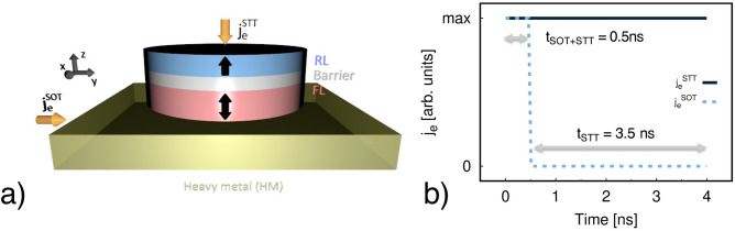
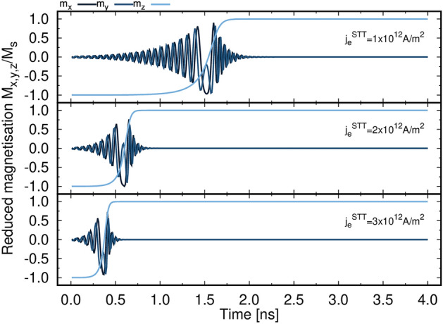
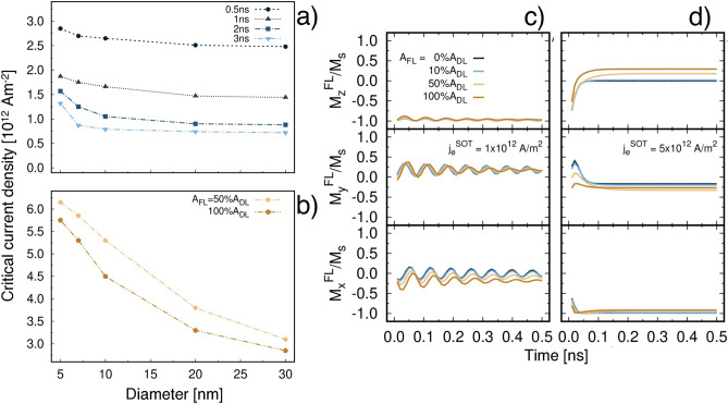
We present a theoretical investigation of the magnetisation reversal process in CoFeB-based magnetic tunnel junctions (MTJs). We perform atomistic spin simulations of magnetisation dynamics induced by combination of spin orbit torque (SOT) and spin transfer torque (STT). Within the model the effect of SOT is introduced as a Slonczewski formalism, whereas the effect of STT is included via a spin accumulation model. We investigate a system of CoFeB/MgO/CoFeB coupled with a heavy metal layer where the charge current is injected into the plane of the heavy metal meanwhile the other charge current flows perpendicular into the MTJ structure. Our results reveal that SOT can assist the precessional switching induced by spin polarised current within a certain range of injected current densities yielding an efficient and fast reversal on the sub-nanosecond timescale. The combination of STT and SOT gives a promising pathway to improve high performance CoFeB-based devices with high speed and low power consumption.


Conflict of interest statement

The authors declare no competing interests.

Figures

Figure 1
Figure 1
(a) Sketch illustrating the investigated system. Brass colour depicts the heavy metal (HM), red and light blue represent the free layer (FL) and reference layer (RL) of the MTJ respectively, light grey refers to the MTJ barrier. jeSOT and jeSTT (yellow arrows) are the current densities injected in the HM and MTJ, respectively. jeSTT is injected along the y-direction, jeSTT is perpendicular to the structure along the z-direction. (b) Simulation protocol: initially both jeSOT (dashed light blue line) and jeSTT (solid black line) are injected for 0.5 ns. After 0.5 ns jeSOT is switched off and only jeSTT is injected into the system in the next 3.5 ns.
Figure 2
Figure 2
Time evolution of the magnetisation components of a 20 nm diameter MTJ for jeSTT 1×1012,2×1012and3×1012Am-2.
Figure 3
Figure 3
(a) Plot of the critical current density for STT switching jcSTT as a function of MTJ diameter for different pulse widths. (b) Plot of the critical current density for SOT switching jcSOT as a function of different strengths of the SOT field-like component (AF) with respect to the damping-like term (AD). For AF=0% and 10% jcSOT could not be determined. Time evolution of the magnetisation components of a 20 nm diameter MTJ as a function of AF for jeSOT 1×10¹²Am-2 (c) and 5×10¹²Am-2 (d) in absence of jeSTT.
Figure 4
Figure 4
(a) Time evolution of the reduced z-component of the magnetisation as a function of jeSOT for jeSTT=1×1011,1×1012and5×1012Am-2. In this case AF=AD and the diameter is 20 nm. (b) Write energy and c) write energy × total switching time as a function of jeSTT and jeSOT for AF=AD and diameter of 20 nm. The palette represents the energy in (b) and energy × switching time in (c), and ranges from blue (low) to yellow (high). White regions correspond to combinations of jeSTT and jeSOT that yield no switching.
Figure 5
Figure 5
(a) Time evolution of the magnetisation components as a function of AF for jeSOT=jeSTT=1×10¹²Am-2 for a 20 nm MTJ. Plot of total switching time (colour) as a function of jeSTT and jeSOT for AF = 0, 0.1, 0.5 and 1 AD for a 20 nm MTJ in panel (be) respectively. The colour scheme shows the switching time from immediate switching (blue) to no switching (yellow) within 4 ns. Dark grey lines represent mark points with switching time 0.5, 1, 2 and 3 ns.
Figure 6
Figure 6
(a) Calculated amplitudes of the coherent excitation mode m0 of the free layer of a 20 nm MTJ as a function of jeSOT for different jeSTT and AF=0.5AD. (b) and (c) show the calculated amplitudes of m0, m1 (vortex) and m-1 (antivortex) modes of a 30 nm MTJ FL for AF=0.5AD, jeSTT=1×10¹²Am-2 and jeSOT=0, 1×10¹²Am-2, respectively. Insets show snapshots of the z-component of the magnetisation with palette blue (+ 1), green (0), red (− 1).

References

    1. Ikeda S, et al. Magnetic tunnel junctions for spintronic memories and beyond. IEEE Trans. Electron Devices. 2007;54:991–1002. doi: 10.1109/TED.2007.894617. - DOI
    1. Apalkov D, et al. Spin-transfer torque magnetic random access memory (STT-MRAM) J. Emerg. Technol. Comput. Syst. 2013;9:1–35. doi: 10.1145/2463585.2463589. - DOI
    1. Khvalkovskiy AV, et al. Erratum: Basic principles of STT-MRAM cell operation in memory arrays. J. Phys. D Appl. Phys. 2013;46:139601. doi: 10.1088/0022-3727/46/13/139601. - DOI
    1. Kent AD, Worledge DC. A new spin on magnetic memories. Nat. Nanotechnol. 2015;10:187–191. doi: 10.1038/nnano.2015.24. - DOI - PubMed
    1. Dieny B, Goldfarb RB, Lee KJ. Introduction to Magnetic Random-Access Memory. Wiley; 2017.