Review
. 2022 Apr 22;15(8):e202200027.
doi: 10.1002/cssc.202200027. Epub 2022 Mar 24.

What is Next in Anion-Exchange Membrane Water Electrolyzers? Bottlenecks, Benefits, and Future

Affiliations
Review

What is Next in Anion-Exchange Membrane Water Electrolyzers? Bottlenecks, Benefits, and Future

Carlo Santoro et al. ChemSusChem. .

Abstract

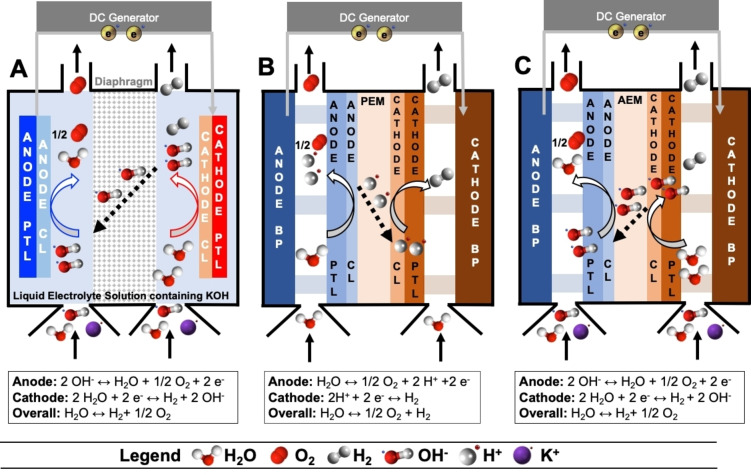
As highlighted by the recent roadmaps from the European Union and the United States, water electrolysis is the most valuable high-intensity technology for producing green hydrogen. Currently, two commercial low-temperature water electrolyzer technologies exist: alkaline water electrolyzer (A-WE) and proton-exchange membrane water electrolyzer (PEM-WE). However, both have major drawbacks. A-WE shows low productivity and efficiency, while PEM-WE uses a significant amount of critical raw materials. Lately, the use of anion-exchange membrane water electrolyzers (AEM-WE) has been proposed to overcome the limitations of the current commercial systems. AEM-WE could become the cornerstone to achieve an intense, safe, and resilient green hydrogen production to fulfill the hydrogen targets to achieve the 2050 decarbonization goals. Here, the status of AEM-WE development is discussed, with a focus on the most critical aspects for research and highlighting the potential routes for overcoming the remaining issues. The Review closes with the future perspective on the AEM-WE research indicating the targets to be achieved.

Keywords: anion-exchange membrane; electrocatalysis; electrolyzers; platinum-group metal-free; water electrolysis.


Conflict of interest statement

The authors declare no conflict of interest.

Figures

Figure 1
Figure 1
Schematic of (A) A‐WE, (B) PEM‐WE, and (C) AEM‐WE. PEM is the proton‐exchange membrane, AEM is the anion‐exchange membrane, CL is the catalyst layer, PTL is the porous transport layer, BP is the bipolar plate. A‐WE operates with concentrated KOH liquid electrolyte that is recirculated. PEM‐WE operates with pure water. AEM‐WE currently operates with diluted KOH or K2CO3 with the possibility for the future of operating with pure water while maintaining high performance.
Figure 2
Figure 2
Approaches to improve AEM‐WEs considering PGM‐free electrocatalysts, AEMs/AEIs, MEA integration, performance, and durability/stability. The schematic related to the AEM based on a quaternary ammonium pendant functional groups and with highlighted the OH path (top right) was adapted from Ref. [54] under CC BY‐NC‐ND 4.0 (https://creativecommons.org/licenses/by‐nc‐nd/4.0/). An example of synthesis schematic (top left) of a PGM‐free electrocatalyst for HER was adapted with permission from Ref. [101]; copyright 2021, American Chemical Society. The figure related to the HER activity for M−N−C and N−C eectrocatalysts at pH 13 (middle left) was adapted from Ref. [102] under CC BY 4.0 (https://creativecommons.org/licenses/by/4.0/).
Figure 3
Figure 3
Identified degradation routes of different cationic functional groups: benzyltrimethylammonium, imidazolium, and phosphonium. Adapted with permission from Ref. [86]; copyright 2018, Elsevier.
Figure 4
Figure 4
Schematic of the (A) HER and (B) OER reaction steps in alkaline environment.
Figure 5
Figure 5
(A) Exchange current densities [log(i 0)] on monometallic surfaces as a function of the calculated hydrogen binding energy. (B) Volcano curve for HER electrocatalysts at various metals in function of the energy of adsorption ΔG ad. OER theoretical overpotential vs. the differences between the standard free energy of two subsequent intermediates ΔG 0 O*−ΔG 0 HO considering (C) various binary oxides and (D) perovskite oxide. (A) Reproduced with permission from Ref. [97];copyright 2013, Royal Society of Chemistry. (B) Adapted from Ref. [98] under CC BY 4.0 (https://creativecommons.org/licenses/by/4.0/). (C,D) Adapted with permission from Ref. [99]; copyright 2011, Wiley‐VCH.
Figure 6
Figure 6
(A) Effect of anolyte feed on the AEM‐WE performance for a CuCoO x anode and with otherwise same operating conditions, cathode, and electrode preparation. (B) Scheme of an anode structure composed mainly of a catalyst–liquid interface and with a minor presence of catalyst‐AEI interface. (C) Effect of the electrochemical potential on the electronic conductivity of thin‐film oxyhydroxide films in 1 m KOH. (A) Adapted from Ref. [125] under CC BY 4.0 (https://creativecommons.org/licenses/by/4.0/). (C) Reproduced with permission from Ref. [131]; copyright 2015, American Chemical Society.

References

    1. Atanassov P., Di Noto V., McPhail S., Electrochem. Soc. Interface 2021, 30, 57–60.
    1. Kusoglu A., Electrochem. Soc. Interface 2021, 30, 44–48.
    1. https://ec.europa.eu/energy/sites/ener/files/hydrogen strategy.pdf.
    1. Kamlungsua K., Su P.-C., Chan S. H., Fuel Cells 2020, 20, 644–649.
    1. Buttler A., Spliethoff H., Renewable Sustainable Energy Rev. 2018, 82, 2440–2454.