Review
. 2022 Feb 22;11(5):1165.
doi: 10.3390/jcm11051165.

Ultrasound and Photoacoustic Imaging of Breast Cancer: Clinical Systems, Challenges, and Future Outlook

Affiliations
Review

Ultrasound and Photoacoustic Imaging of Breast Cancer: Clinical Systems, Challenges, and Future Outlook

Karl Kratkiewicz et al. J Clin Med. .

Abstract

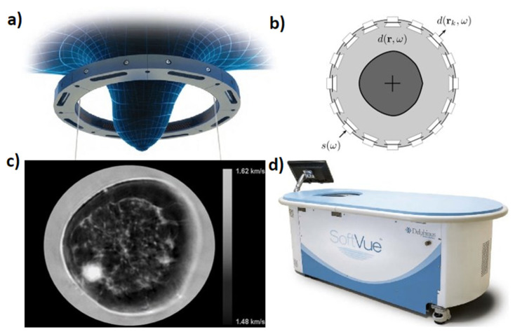
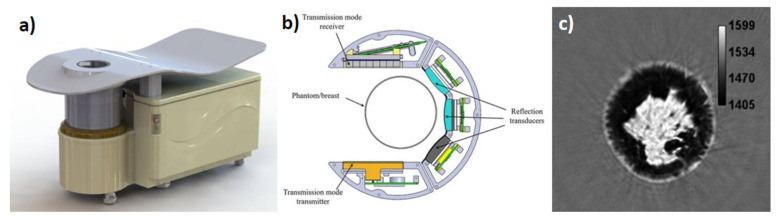
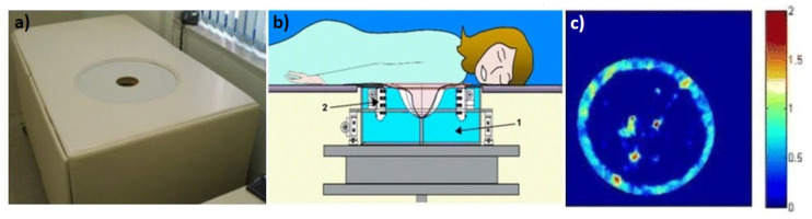
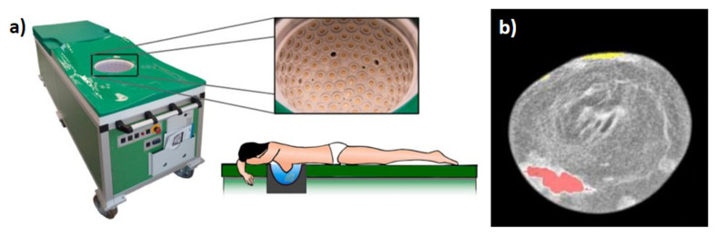
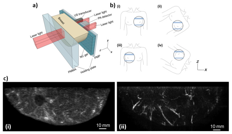
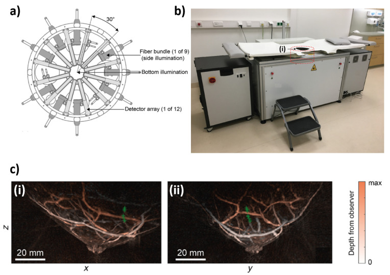
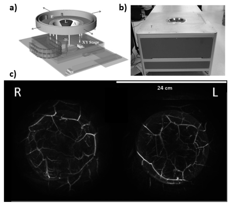
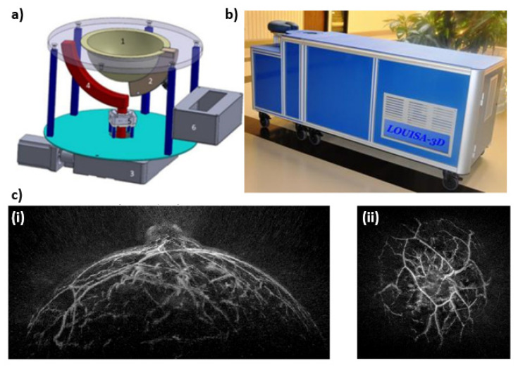
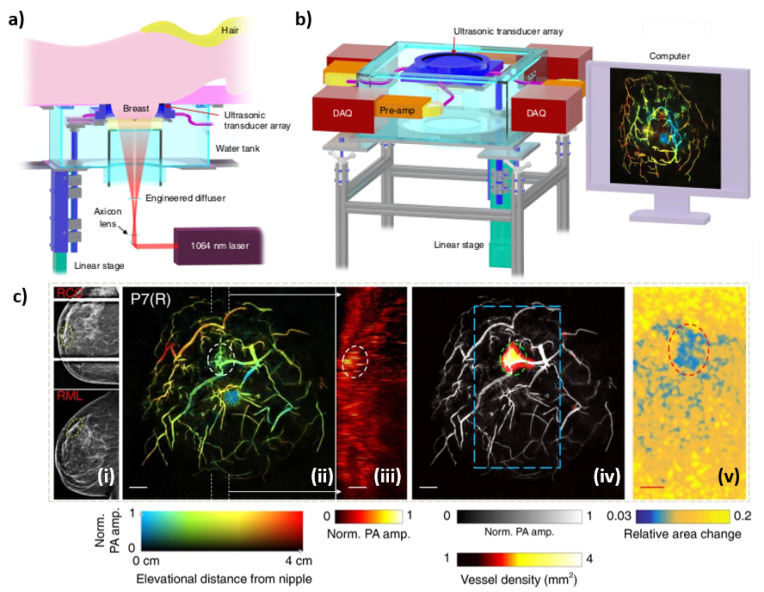
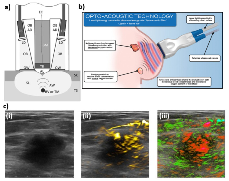
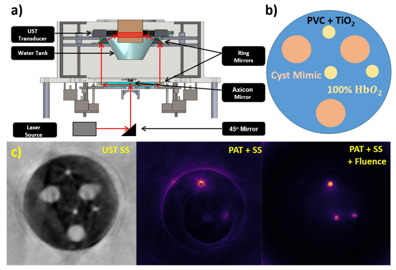
Presently, breast cancer diagnostic methods are dominated by mammography. Although drawbacks of mammography are present including ionizing radiation and patient discomfort, not many alternatives are available. Ultrasound (US) is another method used in the diagnosis of breast cancer, commonly performed on women with dense breasts or in differentiating cysts from solid tumors. Handheld ultrasound (HHUS) and automated breast ultrasound (ABUS) are presently used to generate reflection images which do not contain quantitative information about the tissue. This limitation leads to a subjective interpretation from the sonographer. To rectify the subjective nature of ultrasound, ultrasound tomography (UST) systems have been developed to acquire both reflection and transmission UST (TUST) images. This allows for quantitative assessment of tissue sound speed (SS) and acoustic attenuation which can be used to evaluate the stiffness of the lesions. Another imaging modality being used to detect breast cancer is photoacoustic tomography (PAT). Utilizing much of the same hardware as ultrasound tomography, PAT receives acoustic waves generated from tissue chromophores that are optically excited by a high energy pulsed laser. This allows the user to ideally produce chromophore concentration maps or extract other tissue parameters through spectroscopic PAT. Here, several systems in the area of TUST and PAT are discussed along with their advantages and disadvantages in breast cancer diagnosis. This overview of available systems can provide a landscape of possible intersections and future refinements in cancer diagnosis.

Keywords: breast cancer; breast imaging; diagnostic imaging; photoacoustic imaging; screening; ultrasound.


Conflict of interest statement

The authors declare no conflict of interest.

Figures

Figure 1
Figure 1
Delphinus Medical Technologies’ SoftVue system (a) Ring transducer used for data acquisition, (b) transducer ring configuration, (c) example of a sound speed (SS) cross sectional slice with darker pixels representing lower SS and brighter pixels representing higher SS, (d) the clinical system.
Figure 2
Figure 2
QT Ultrasound scanner 2000 (a) the full clinical system, (b) top view of reflection and transmission array platform, (c) example of an SS cross sectional slice with darker areas representing lower SS and brighter pixels.
Figure 3
Figure 3
Mastoscopia’s MUT Mark II system (a) the full clinical system, (b) rotating transmitter and system assembly used for imaging showing (1) scanning chamber and (2) transmitter/receiver array, (c) color composite image generated by using ‘refractivity’, attenuation and dispersion values with adipose tissue and normal breast parenchyma producing lower values less than 1, while tumors would produce values closer to 2.
Figure 4
Figure 4
Design by Karlsruhe Institute for Technology: (a) the clinical system showing patient laying prone along with close-up of ellipsoid tank with transducer array elements each containing four emitters and nine receivers, (b) example fusion reflectivity, SS, and attenuation image. Red and yellow overlay denoting suspected malignant and benign tissue, respectively.
Figure 5
Figure 5
(a) Schematic illustration of the breast-holding structure. (b) Schematic illustration of breast-holding direction: (i) cranio-caudal (CC) of left breast, (ii) medio-lateral-oblique (MLO) of left breast, (iii) CC of right breast, and (iv) MLO of right breast. (c) Lesion images of a breast in (i) ultrasound and (ii) photoacoustic modes.
Figure 6
Figure 6
(a) Schematic of the Twente PAM 2 imaging tank. (b) Photograph of the Twente photoacoustic mammography (PAM) 2 system—(i) is the imaging tank. (c) Local maximum intensity projections of a breast in the (i) sagittal and (ii) transverse plane.
Figure 7
Figure 7
(a) Drawing showing the hemispherical array (A) mounted on a two-axis translational stage (XY). The hemispherical array and an extension (E) are filled with degassed water. Laser light is fed from the bottom of the array via an articulating arm (not shown) through a negative lens that diverges the laser light (L) to a diameter of −60 mm at the breast surface. (b) Photograph of PAM scanner showing the exam table (T) and the breast positioning cup (C), below which is located the hemispherical detector array. (c) Maximum amplitude projection images of a breast for both right (R) and left (L) sides.
Figure 8
Figure 8
(a) Imaging module capable of scanning large breast consisting of (1) Imaging bowl that contains acoustic coupling medium and breast, (2) Optoacoustic transducer array, (3) Large motor to rotate the entire imaging module around the breast, (4) Arc-shaped optical fiber to illuminate the breast with homogeneous beam of light, (5) Small motor to rotate the arc-shaped fiberoptic paddle around the imaging bowl, and (6) preamplifier boards directly connected to the probe. (b) Photograph of the Laser Optoacoustic Ultrasonic Imaging System Assembly (LOUISA-3D) system designed as an examination bed. (c) Maximum amplitude projection images of the breast—(i) sagittal projection, and (ii) coronal projection.
Figure 9
Figure 9
(a) Overview of the SBH-PACT system. (b) Perspective view of the system with patient bed and optical components removed. DAQ: data acquisition system, Pre-amp: pre-amplifier circuits. (c) X-ray and photoacoustic (PA) images of a 44-year-old female patient with a fibroadenoma in the right breast—(i) X-ray mammograms of the affected breasts, (ii) Depth-encoded angiograms, (iii) Maximum amplitude projection images of thick slices in sagittal planes marked by white dashed lines in (ii), (iv) Automatic tumor detection on vessel density maps, and lastly (v) PA elastography images.
Figure 10
Figure 10
(a) Schematic diagram of the Imagio system. Tissue (TS), skin (SK), scattered light (SL), optical beams (OB), fiber bundles (FB), light diffusers (LD), optical windows (OW), acoustic waves (AW), blood vessels or tumors (BV or TM), acoustic lens (AL), transducers (TR), electrical cables (EC), backing material (BM). (b) Illustration shows that laser light emitted at wavelengths corresponding to absorption peaks of oxygenated and deoxygenated hemoglobin produces acoustic signals that can then be used to reconstructed oxygen saturation maps. (c) An example of combined ultrasound/photoacoustic images of breast carcinoma—(i) An ultrasound gray scale image of a 2.6 cm malignant mass, (ii) regions of increased total hemoglobin, and (iii) oxygenation map where red are regions below an average oxygen saturation of 85% while green are normally oxygenated regions (>90% sO2).
Figure 11
Figure 11
Our USPAT system prototype (a) Full system schematic, (b) heterogeneous phantom structure, (c) original SS image used for compensations, PAT image with SS compensation, PAT image with SS and fluence compensation. PVC: polyvinyl chloride, HbO2: oxygenated hemoglobin.

References

    1. Sung H., Ferlay J., Siegel R.L., Laversanne M., Soerjomataram I., Jemal A., Bray F. Global cancer statistics 2020: GLOBOCAN estimates of incidence and mortality worldwide for 36 cancers in 185 countries. CA Cancer J. Clin. 2021;71:209–249. doi: 10.3322/caac.21660. - DOI - PubMed
    1. World Health Organization Breast Cancer. [(accessed on 29 January 2022)]. Available online: https://www.who.int/news-room/fact-sheets/detail/breast-cancer.
    1. Gøtzsche P.C., Jørgensen K.J. Screening for breast cancer with mammography. Cochrane Database Syst. Rev. 2013 doi: 10.1002/14651858.CD001877.pub5. - DOI - PMC - PubMed
    1. Brodersen J., Siersma V.D. Long-term psychosocial consequences of false-positive screening mammography. Ann. Fam. Med. 2013;11:106–115. doi: 10.1370/afm.1466. - DOI - PMC - PubMed
    1. American Cancer Society . Cancer Facts & Figures 2021. American Cancer Society; Atlanta, GA, USA: 2021. [(accessed on 29 January 2022)]. Available online: https://www.cancer.org/content/dam/cancer-org/research/cancer-facts-and-....

LinkOut - more resources