

Ag Surface and Bulk Segregations in Sputtered ZrCuAlNi Metallic Glass Thin Films
- PMID: 35268865
- PMCID: PMC8910967
- DOI: 10.3390/ma15051635
Ag Surface and Bulk Segregations in Sputtered ZrCuAlNi Metallic Glass Thin Films
Abstract
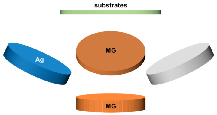
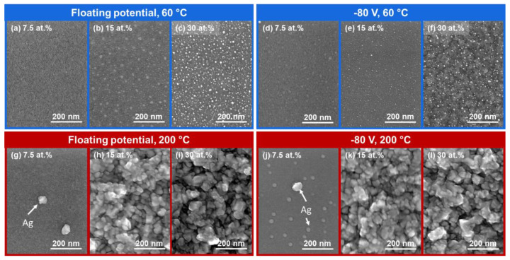
We report on the formation of Ag-containing ZrCuAlNi thin film metallic glass (nano)composites by a hybrid direct-current magnetron sputtering and high-power pulsed magnetron sputtering process. The effects of Ag content, substrate temperature and substrate bias potential on the phase formation and morphology of the nanocomposites were investigated. While applying a substrate bias potential did not strongly affect the morphological evolution of the films, the Ag content dictated the size and distribution of Ag surface segregations. The films deposited at low temperatures were characterized by strong surface segregations, formed by coalescence and Ostwald ripening, while the volume of the films remained featureless. At higher deposition temperature, elongated Ag segregations were observed in the bulk and a continuous Ag layer was formed at the surface as a result of thermally enhanced surface diffusion. While microstructural observations have allowed identifying both surface and bulk segregations, an indirect method for detecting the presence of Ag segregations is proposed, by measuring the electrical resistivity of the films.
Keywords: electrical resistivity; nanocomposites; segregation; thin film metallic glass.
Conflict of interest statement
The authors declare no conflict of interest. The funders had no role in the design of the study; in the collection, analyses, or interpretation of data; in the writing of the manuscript, or in the decision to publish the results.
Figures


References
-
- Bhat A., Budholiya S., Raj S.A., Sultan M.T.H., Hui D., Shah A.U.M., Safri S.N.A. Review on nanocomposites based on aerospace applications. Nanotechnol. Rev. 2021;10:237–253. doi: 10.1515/ntrev-2021-0018. - DOI
-
- Calderon Velasco S., Cavaleiro A., Carvalho S. Functional properties of ceramic-Ag nanocomposite coatings produced by magnetron sputtering. Prog. Mater. Sci. 2016;84:158–191. doi: 10.1016/j.pmatsci.2016.09.005. - DOI
-
- Guo J., Zhao X., Herisson De Beauvoir T., Seo J.-H., Berbano S.S., Baker A.L., Azina C., Randall C.A. Recent Progress in Applications of the Cold Sintering Process for Ceramic-Polymer Composites. Adv. Funct. Mater. 2018;28:1801724. doi: 10.1002/adfm.201801724. - DOI
-
- Ju H., Yu D., Yu L., Ding N., Xu J., Zhang X., Zheng Y., Yang L., He X. The influence of Ag contents on the microstructure, mechanical and tribological properties of ZrN-Ag films. Vacuum. 2018;148:54–61. doi: 10.1016/j.vacuum.2017.10.029. - DOI
-
- Hong C., Huan Y., Zhang P., Zhang K., Dai P. Effect of silver content on the microstructure, thermal stability and mechanical properties of CrNx/Ag nanocomposite films. Ceram. Int. 2021;47:25324–25336. doi: 10.1016/j.ceramint.2021.05.254. - DOI
Grants and funding
LinkOut - more resources
Full Text Sources
