. 2022 Mar 31;185(7):1240-1256.e30.
doi: 10.1016/j.cell.2022.02.017. Epub 2022 Mar 18.

Large-scale two-photon calcium imaging in freely moving mice

Affiliations

Large-scale two-photon calcium imaging in freely moving mice

Weijian Zong et al. Cell. .

Abstract

We developed a miniaturized two-photon microscope (MINI2P) for fast, high-resolution, multiplane calcium imaging of over 1,000 neurons at a time in freely moving mice. With a microscope weight below 3 g and a highly flexible connection cable, MINI2P allowed stable imaging with no impediment of behavior in a variety of assays compared to untethered, unimplanted animals. The improved cell yield was achieved through a optical system design featuring an enlarged field of view (FOV) and a microtunable lens with increased z-scanning range and speed that allows fast and stable imaging of multiple interleaved planes, as well as 3D functional imaging. Successive imaging across multiple, adjacent FOVs enabled recordings from more than 10,000 neurons in the same animal. Large-scale proof-of-principle data were obtained from cell populations in visual cortex, medial entorhinal cortex, and hippocampus, revealing spatial tuning of cells in all areas.

Keywords: entorhinal cortex; freely moving; grid cells; head direction cells; hippocampus; mice; miniature microscopy; place cells; space; two-photon imaging; visual cortex.


Conflict of interest statement

Declaration of interests The authors declare no competing interests.

Figures

None
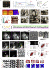
Graphical abstract
Figure 1
Figure 1
Flexible cable and low weight of MINI2P improves free-foraging behavior of mice (A) Representative trajectories of 3 mice running in a 80 × 80 cm2 open field, with 3 trials per mouse: control (no miniscope or cable), 3 g dummy miniscope + thin connection cable assembly (3g-t), and 5 g dummy + thick connection cable assembly (5g-T). Trajectories are shown for trials with total running distance corresponding to the 20th, 50th, and 80th percentile of values for all trials in the 5g-T condition (top to bottom). Red dashed boxes show 30 × 30 cm2 square used in Diii. Thick black line, cue card. (B) Accumulated distance over 30 min of running. Lines, mean across 10 mice; vertical bars, SD at 6 time points. Shaded region, SD at all time points. Note similarity between 3g-t and control group. (C) Cumulative speed distribution over 30 min of running. Each curve shows one trial. Color indicates experimental condition. (D) Box plot showing total distance traveled (i), median speed (ii), and distance traveled in central 30 cm square (iii) in each condition (30 min each). Horizontal lines indicate median, boxes interquartile range, and whiskers 1.5 × interquartile range. Colored dots, individual animals. Conditions are compared using a Friedman test followed by Tukey post hoc tests, p < 0.05, ∗∗p < 0.01, and ∗∗∗p < 0.001. (E) Reduced turning behavior in 5g-T condition. (i) Representative trajectories during fast running (frames with speed exceeding 75th percentile, or 7.3 cm/s). Color indicates momentary tortuosity (curvedness) of mouse trajectory. Median and 75th percentile tortuosity are shown (ii and iii). See also Figure S1.
Figure S1
Figure S1
Behavioral impact of MINI2P as a function of body weight, age, and sex, and contribution of cable thickness versus microscope weight, related to Figure 1 (A) There was no clear linear relationship between total distance traveled (i and ii) and median speed (iii and iv), on one hand, and animal body weight (i and iii) and age (ii and iv), on the other hand, in any condition. R2 was calculated from linear regression between each pair of factors. Each dot indicates one recording. Color of dots indicates the sex of the mouse in that recording: blue for male and orange for female. (B) Additional behavior analysis in Figure 1. (i) 90th percentile speed, and (ii) time spent within the central 30 cm square of the open field in each condition (30 min each). Colored dots represent individual animals. Conditions are compared using a Friedman test followed by Tukey post hoc test, p < 0.05, ∗∗p < 0.01, and ∗∗∗p < 0.001. (iii) Schematic of tortuosity analysis. Total path length within a time segment was compared with the Euclidean distance between the start and end point of the window. (iv–vii) The time spent on turning was defined as the total time of frames with tortuosity above the 75th percentile tortuosity value computed from all frames in control recordings with no miniscope and no cable (a value of 1.9). This time was reduced in the 5g-T group but not in the 3g-t group (n = 10 in each condition; Friedman test on data from all three experimental conditions: χ2 = 6.2, p = 0.045; post-hoc Tukey t test for 5g-T versus 3g-t, p < 0.001, 5g-T versus control: 0.025; 3g-t versus control: 0.136). Running speed during turning moments was lower in the 5g-T experiment than in 3g-t and control (n = 10 in each condition; Friedman test: χ2 > 12.6, p < 0.0018; post-hoc Tukey test for 5g-T versus each of the other groups: p < 0.018; 3g-t versus control: p > 0.493). (iv) Representative turning trajectories in three experiments in which frames with tortuosity lower than the 75th percentile over all values for tortuosity were removed. Color scale shows value of momentary speed during turning. (v) Total time spent on turning (tortuosity >75th percentile) across the three experiments. (vi) Median speed and (vii) 75th percentile speed during turning (tortuosity >75th percentile). (C) Isolating the effect of fiber thickness (flexibility) on behavior (n = 20 animals). Control: no dummy or cable, 3g-t: 3 g microscope and thin connection cable assembly, and 3g-T: 3 g microscope and thick connection cable assembly. Friedman test on data from all three experimental conditions, total running distance: χ2 = 30.1, p < 0.0001; median running speed: χ2 = 24.3, p < 0.0001; 90th percentile running speed: χ2 = 31.6, p < 0.0001; total running distance in center: χ2 = 24.4, p < 0.0001; total running time in center: χ2 = 6.3, p = 0.043; post-hoc Tukey tests for 3g-T versus control: p < 0.001 (total running distance, median running speed, 90th percentile running speed, and total running distance in center) or p = 0.130 (total running time in center); post-hoc Tukey tests for 3g-T versus 3g-t: p < 0.001 (total running distance, median running speed, 90th percentile running speed, and total running distance in center) and p = 0.085 (total running time in center); post-hoc Tukey tests for 3g-t versus control: p = 0.726 (total running distance); p > 0.90 (median running speed), p = 0.490 (90th percentile running speed), p > 0.90 (total running distance in center), p > 0.90 (total running time in center). Differences in running time in the center did not reach statistical significance because several mice with thick cables stopped and rested in the middle of the box (where the strain of the cable was smaller than in the periphery). (i) As in Figure S1B, (ii) as in Figure 1Di, (iii) as in Figure 1Dii, (iv) as in Figure S1Bi, (v) as in Figure 1Diii, and (vi) as in in Figure S1Bii. (D) Isolating the effect of microscope weight on behavior (n = 10). Control: no dummy or cable, 3g-t: 3 g miniscope and thin connection cable assembly, and 5g-t: 5 g miniscope and thin connection cable assembly. Friedman test on data from all three experimental conditions, total running distance: χ2 = 9.8, p = 0.0074; median running speed: χ2 = 6.2, p = 0.045; 90th percentile running speed: χ2 = 11.4, p = 0.003; total running distance in center: χ2 = 7.2, p = 0.027; total running time in center: χ2 = 5.6, p = 0.061; post-hoc Tukey tests for 5g-t versus control, p = 0.128 (total running distance); p = 0.269 (median running speed); p = 0.078 (90th percentile running speed), p = 0.007 (total running distance in center), and p = 0.048 (total running time in center); Tukey tests for 5g-t versus 3g-t: p = 0.187 (total running distance); p = 0.421 (median running speed); p = 0.107 (90th percentile running speed), p = 0.067 (total running distance in center), and p = 0.319 (total running time in center); Tukey tests for 3g-t versus control: p > 0.90 (total running distance); p > 0.90 (median running speed); p = 0.618 (90th percentile running speed); p = 0.618 (total running distance in center); and p = 0.563 (total running time in center). (i) As in Figure 1B, (ii) as in Figure 1Di, (iii) as in Figure 1Dii, (iv) as in Figure S1Bi, (v) as in Figure 1Diii, and (vi) as in Figure S1Bii. Definitions in box plots are the same as in Figure 1.
Figure 2
Figure 2
MINI2P enables large-scale 2P calcium imaging in multiple brain regions (A) Key features of the MINI2P microscope. (i) Schematic of MINI2P with key components. (ii) Quartet design of μTlens consisting of four stacked piezo-membrane lenses. (iii) Axial scanning range of MINI2P with quartet μTlens. (iv) Structure of tapered fiber bundle (TFB). (v) Customized objectives for 3 different imaging applications. (B) Imaging in visual cortices (VC) of a GCaMP6s transgenic mouse running in an open enclosure as in Figure 1. (i) Mounting of MINI2P microscope on top of cover glass to image L2/L3 neurons in VC. (ii) Example of MINI2P imaging (maximum intensity projection) in VC; 592 neurons were extracted in a single plane of one FOV. (iii) Ten example calcium traces from neurons marked by red circles in (ii). Red parts of traces identify suprathreshold calcium transients. (iv–vi) Violin plots showing motion artifact and correction quality from MINI2P recordings in VC. Outline of each violin plot: probability density smoothed by a kernel density estimator; bandwidth: 10% of the data range. Interquartile range and median are indicated by vertical and horizontal lines, respectively. Symbols apply to all subsequent violin plots. (iv) Rigid motion (inter-frame FOV drift) during imaging at low and high running speeds (cutoff 5 cm/s), shown separately for x and y axes of the image. (v) Nonrigid motion (intra-frame FOV drift). (vi) Motion correction quality (average and maximum residual drift for all 30 spatial principal components [SPCs] after applying nonrigid registration. (3 mice and 6 recordings, 10 min each). AP, anterior-posterior; ML, medial-lateral axis (referencing to animal skull). (C) Imaging in MEC of a GCaMP6s transgenic mouse. Symbols as in (B). (i) Top: prism assembly. Bottom: position of MINI2P microscope. The prism was inserted along the dorsoventral surface of MEC between cerebrum and cerebellum, allowing activity in L2/L3 of MEC to be imaged from the back. (ii) Example of MINI2P imaging; 404 MEC neurons were extracted by Suite2P in a single plane of one FOV. (iii) Ten example calcium traces from the neurons marked by red circles in (ii). (iv–vi) Motion artifact and correction quality in MEC. Symbols as in Biv to Bvi. 3 mice and 6 recordings, 10 min each. (D) Imaging in CA1 after local injection of AAV-GCaMP7f in a wild-type mouse. (i) After aspiration of overlying cortex, a 1.0 mm GRIN lens (with a 1.8 mm guide cannula) was implanted to access CA1 from the top of the brain. (ii) Example imaging in CA1; 464 neurons extracted in one FOV. (iii) Ten example calcium traces from the neurons marked by red circles in (ii). (vi–vi) Motion artifact and correction quality in CA1. Symbols as in Biv to Bvi. 3 mice, and 5 recordings, 10 min each. (E) Long-term stability of MINI2P imaging. The same VC cells were tracked for 5 weeks. (i) Maximum intensity projection of 4 recordings across 34 days. Yellow circles indicate 4 example cells identified as the same cells in 4 recordings. (ii) Matrix showing overlap of cell footprints in pairs of recordings. Green: cells extracted in one recording. Pink: cells in the other recording. White: overlapping region. (iii) Matched cells (blue, first recording; orange, second recording) selected by setting an overlap ratio of 0.5. Number (percentage) of matched cells in second compared with first recording is indicated. (iv) Ratio of matched cells/total cells (first recording) versus interval between two recordings. More than 40% matched cells could be identified across an interval of 5 weeks. (v) Forty-eight cells (36% of the cells recorded on day 0) could be identified in all 4 recordings. Color indicates recording from which the cells were extracted. See also Table 1; Figures S2 and S7.
Figure S2
Figure S2
Supplementary features and performance of MINI2P, related to Figure 2 (A) μTlens test. (i) Multiple single Tlenses (top) and an Optotune EL-3-10 (ETL, used in the previous generation of miniscope (Zong et al., 2021), bottom). (ii) Representative step response of the quartet μTlens. (iii) Optical power (diopter) versus control voltage for five quartet μTlens samples. (B) TFB test. (i and ii) Detection efficiency comparison between 1.5 mm SFB, 0.7 mm TFB, and 0.7 mm SFB. (i) Imaging of a uniform fluorescent slide (FSK2, Thorlabs, NJ, USA) with the 1.5 mm SFB (left), 0.7 mm TFB (middle), and 0.7 mm SFB (right). Pixel intensity is color-coded; bright yellow indicates higher intensity; dark purple indicates low intensity. Laser power, PMT sensitivity, and pixel dwell time were identical in the three recordings. (ii) Histograms showing pixel intensity of images in (i). Dashed line indicates baseline of the image (average intensity of the image without exposure).(iii) Picture of SFB (left) and TFB (right). (C) Photos showing mounting of MINI2P miniscope on the head of a mouse. (D) Metrics for motion correction quality for GCaMP (functional) imaging channel. Average and maximum residual drift are shown for all 30 spatial principal components (SPCs) after applying nonrigid registration in Suite2P. Maximum residual drift (xy) in the example recording after motion correction is less than 1.5 μm for all SPCs. (ii) The time course of the amplitude of the 3rd SPC in (i). The top 500 frames (green area) and bottom 500 frames (purple area) in each SPC were used to evaluate the contribution of z drift to this SPC. (iii) Left first column: average image of top 500 frames in (ii). Left second column: average image of bottom 500 frames in (ii). Overlay (the third column) and difference (the fourth column) of the averages of top 500 frames and bottom 500 frames were manually checked for z drift. If any z drift was present, the nucleus and the cytoplasm should display an anticorrelated patten in the two images, which cannot be explained by GCaMP activity. Note that such anticorrelation was not observed in the example SPC (fifth and last column). All SPCs were manually checked before further analysis to ensure no obvious z drift was present. (E) Registering the same cells on different recording days. (i) Pipeline for registering the same cells on different recording days. The pipeline was taken from a published MATLAB package (https://github.com/ransona/ROIMatchPub). Step 1: landmarks were manually labeled in two recordings, and then a transformation was applied to one of the images to match landmarks. Yellow arrows show landmarks (active cells) for registration. Note that in this example data, the same FOV could be revisited after 8 days and after replacing the stitching adapter a total of 4 times. Step 2: the pipeline automatically detects matched cell candidates by setting an overlap ratio (50% in this analysis). Step 3: morphological structure of matched cells was manually checked for filtering out unreliable cell pairs. Note the high anatomical similarity of 52 confirmed matched cells. (ii) On average 49 ± 14% cells could be registered as matched cells with the pipeline (n = 3 mice, 6 recordings, 432 matched cells, also see Methods S1, Section 11). Color in the left plots indicates animals. The same color is applied in the right table. (iii–v) Further validation of the registration reliability by analyzing the linear regression of the ROI area (iii), number of calcium events (iv), and SNR of matched cell pairs. The much higher R2 on all three scores compared with a shuffled distribution indicates high reliability of registration. Shuffled data were generated by randomly picking two cells in each recording, repeating this procedure 4,320 times (10 × 432). (F) Additional analysis for Figure 2E. (i) Ten matched example cells identified in all 4 recordings shown in Figure 2E showing similarity of cell morphology. (ii) Example matched cell, indicated by red box in (i), which shows highly stable spatial tuning across all 4 recordings (symbols as in Figure 4Ai).
Figure 3
Figure 3
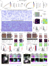
Increasing the cell yield of MINI2P to thousands (A) Three steps to increase the cell yield: enlarging the FOV, multiplane imaging, and stitching of neighboring FOVs. (B) Cell yield after increasing FOV from 420 × 420 μm2 to 500 × 500 μm2. Mean cell numbers ± SD are indicated as black stars and vertical bars, respectively, and in gray text (symbols apply also to C–E). Colored dots denote single recordings; color indicates brain region. (applies also to D and E). For further imaging parameters, see Methods S1; Section 11. (C) Relationship between plane interval and percentage of repeated neurons in VC (0–80 μm within 200 μm from cortical surface, 20 μm steps; 5 min recording, frame rate 20 Hz, stack rate 10 Hz, MINI2P-F, 2 mice, 6 FOVs, 24 planes, 5,602 cells). (D) Two-plane imaging at 40 μm interval in VC and MEC, and in CA1 at 40–60 μm. (i) Repeated cell ratio. (ii) SNR of all cells in plane 1 (shallow) versus plane 2 (deep). Higher fraction of repeated neurons in CA1 reflects degraded z axial resolution with GRIN lenses (Figure S3A). VC, n = 4 mice, 32 FOVs, 12,569 cells; MEC, n = 4 mice, 15 FOVs, 4,728 cells; CA1, n = 3 mice, 5 FOVs, 1,728 cells. (E) Number of nonrepeated cells obtained with 1, 2, or 4 imaging planes in VC (4 mice, 9 FOVs), MEC (6 mice, 9 FOVs), and CA1 (3 mice, 5 FOVs). (F) Four-plane imaging in VC. (i) Maximum intensity projection (planes scanned sequentially; 25 ms per plane); (ii) extracted neurons projected on stack of imaging planes. (G) Three-dimensional imaging of VC neurons in freely moving mice. Volume size 420 × 420 × 160 μm3, volume rate 2 Hz, MINI2P-F. (i) xy and xz max projection of 3D stack data (20 planes). Color indicates imaging depth. (ii) Calcium signals of 5 neurons randomly selected at different imaging depths (colored circles and arrows in (i)). (H) FOV stitching increased cumulative cell yield across successive sessions to over 10,000 in VC. (i) 4.6 mm Window with matrix of 5 × 5 FOVs (yellow squares) superimposed on retinotopic map. Color indicates sine value of angle between vertical (V) and horizontal (H) retinotopic mapping gradients (red: 1; blue: −1). Discrete visual areas can be identified by similar color. (ii) Average image (from plane 2) covering 2.2 × 2.2 mm2. (iii) Two-dimensional projection shows separation of neurons between planes (magenta: −100 μm; blue: −140 μm). See also Figure S3.
Figure S3
Figure S3
Multiplane imaging, distortion correction, and FOV stitching, related to Figure 3 (A) Example data showing removal of repeated cells in VC (i and ii), MEC (iii and iv), and CA1 (v–viii). (i and ii) Example two-plane recording in VC. (i) Cells in plane 1 and plane 2 extracted from Suite2P before removing repeated cells. Left: bright green shows footprints of all cells extracted from plane 1. Middle: bright purple shows footprints of all cells extracted in plane 2. Right: overlay of cells in planes 1 and 2; overlapping cell footprints are shown in white. (ii) Twenty-one cells or 6% were removed from two planes. Left: bright green shows remaining cells in plane 1, dark green shows removed cells in plane 1. Middle: bright purple shows remaining cells in plane 2, dark purple shows removed cells in plane 2. Right: overlay of remaining cells in planes 1 and 2. (iii and iv) Example two-plane recording in MEC. Definitions are as in (i and ii). Forty-one cells or 7% were removed from two planes. (v to ix) Example two-plane recording in CA1. (v) Due to the strong aberration of GRIN lenses, the z resolution of the CA1 imaging was a lot lower than during imaging from VC and MEC. Therefore, many cells were duplicated across the two planes, even at an interval of 60 μm (repeated cells). Yellow arrows show three examples of repeated cells. Criteria for counting repeated cells are shown to the right. (vi) Many cells directly extracted from Suite2P are repeated cells, expressed by overlap of cell footprints from the two layers (white regions in the right panel). (vii) After 127 repeated cells were removed, overlap of cell footprints from the two CA1 planes was minimized (note less overlap [white] than in vi). (viii) Calcium signals from 25 pairs of repeated cells. Green trace is from plane 1 and purple trace is from plane 2. In each case, the cell with highest calcium activity (mean ΔF/F) was kept, whereas the cell from the other plane was removed. Note high correlation of calcium activity in each repeated cell pair. (B) A series of stitching adapters added between the MINI2P scopebody and the baseplate allow shifting of the FOV even after the baseplate is permanently fixed on the head of the animal. Accurate and repeatable FOV shifts in up to 400 μm steps are achieved by replacing stitching adapters. (D) Imaging quality of 25 FOVs shown in Figure 3H. (i) Calcium signals of 25 neurons randomly selected from each FOV. Color indicates FOV from which the neurons were selected. (ii) Numbers of cells and FOVs (in brackets) recorded on 11 consecutive days. (iii) SNR of all cells recorded on each day. (C) Step-by-step illustration of the distortion correction procedure. The dark corners in the FOV are caused by the fact that the scanning field of MINI2P has already reached the limit of the objective aperture.
Figure 4
Figure 4
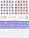
Spatial tuning features of 4,786 visual cortex neurons (A) Place-modulated cells (PCs) in visual cortex (VC). (i to iii) Example PC. (i) Top: spatial tuning in an example PC (full 30 min, first half, second half), displayed as intensity of calcium activity (ΔF/F per second, color scale). Spatial bins: 2.5 × 2.5 cm2; 3 cm Gaussian smoothing kernel. Numbers on top indicate peak activity (ΔF/F×s-1). Bottom: animal trajectory with calcium events superimposed (in red). Size of red spots indicates amplitude of deconvolved calcium events (see STAR Methods). Definitions in (i) apply to all subsequent spatial tuning maps. (ii) Spatial information content of the example PC (red bar) exceeds 95th percentile (blue bar) of shuffled data (gray bars, 200 iterations). (iii) Spatial tuning map correlation (first versus second half) compared with shuffled data. (iv) Percentage of PCs in the recorded data (red bar, 293 cells) compared with shuffled data for all cells (dashed lines, min and max percentage). (v) Spatial information content for observed (orange) versus shuffled (gray) data. (vi) Similar plot for half-session spatial correlations. (vii) Distribution of PCs (dots) across matrix of FOVs. Spatial information content is color-coded (gray, cells that did not meet PC criteria [no-PCs]). (B) Head direction-modulated cells (HDCs) in VC. (i–iii) Example HDC. (i) Top: directional tuning map showing calcium activity as a function of head direction (HD). Faint gray lines show head direction occupancy; black lines show calcium activity as a function of head direction. Bottom: mouse trajectory (in gray) with calcium events superimposed (same cell). Events are color-coded by head direction, size of spots indicates amplitude. (ii) MVL of the example HDC (red bar) compared with shuffled data, as in Aii. (iii) Half-session directional correlations, as in Aiii. (iv) Percentage of HDCs, as in Aiv. (v) MVL for observed (orange) versus shuffled (gray) data. (vi) Half-session directional correlations for observed and shuffled data. (vii) Distribution of HDCs (dots) across FOVs, with MVL color-coded and cells not passing HDC criteria in gray (no-HDC). See also Figure S4.
Figure S4
Figure S4
Supplementary for spatial tuning analysis in VC, related to Figure 4 (A) Mouse #96766. Trajectory versus head direction for 25 recordings. (B) Mouse #96766.Trajectory vs. movement speed for 25 recordings. (C) Metrics of behavior for 25 recordings (different FOVs) in mouse # 96766. (i) Accumulated distance across each recording over 30 min (22 recordings), or 40 mins (3 recordings) of continuous running. Each line denotes one recording. Color indicates number of the recording (FOV). Same color definition applies in iv and vii. (ii) Total distance traveled and (iii) coverage of the arena in all 25 recordings (mean cell numbers ± SD are indicated). Black stars indicate mean value. Color dots denote single recordings. Same definition applies in v and vi. (iv) Cumulative speed distribution showing fraction of time spent at different running speeds in all 25 recordings. (v) Median running speed and (vi) 90th percentile running speed in all 25 recordings. (vii) Head direction occupancy across each recording. Peak occupancy time is indicated. (D) Spatial tuning maps of n = 100 example place-modulated cells (PC) for mouse #96766. PCs are ranked by spatial information (SI) and PCs with higher SI are on top. The colormap definition is the same as in Figures S2Fii and 4Ai. (F) Head directional tuning maps of n = 100 example head direction-modulated cells (HDCs) for mouse #96766. HDCs are ranked by MVL and HDCs with higher MVL are on top.
Figure S5
Figure S5
Metrics of behavior for MEC recordings and additional features of grid cells in MEC and PCs in CA1, related to Figure 5 (A) Metrics of behavior for 5 recordings (different FOVs) in Figure 5. (i) Accumulated distance across each recording over 60 min of continuous running. Each line denotes one recording. Color indicates the number of the recording (FOV). Same color definition applies in (ii) to (vi). (ii) Total distance traveled and (iii) coverage of the arena in all 25 recordings (mean cell numbers ± SD are indicated). Black stars indicate mean value. Color dots denote single recordings. Same definition applies in v and vi. (iv) Cumulative speed distribution in all 5 recordings. (v) Median running speed. (vi) 90th percentile running speed in all 5 recordings. (B) Grid cells in an MEC example mouse (Mouse #97045). Grid cells were plotted (in i and ii) in sequence of grid scores. Upper rows show grid cells with the highest grid scores. (i) Plots showing spatial location of calcium events (without animal’s trajectory) for 310 grid cells (same grid cells in Figure 5). Size of spots indicates amplitude of individual calcium event. (ii) Spatial tuning maps for the same cells as in (i). Color code in each map is scaled to peak calcium activity. (C) An example conjunctive grid × head direction-modulated cell. Top left: animal trajectory (in gray) with calcium events superimposed (in color). Events are color-coded by head direction, size of spots indicates the amplitude of deconvolved calcium events. Top right: directional tuning map showing localized calcium activity as a function of head direction (HD). Faint gray lines show head direction occupancy across each recording. Black lines show the intensity of calcium activity as a function of head direction in polar coordinates. Tuning curve was normalized by the peak calcium activity, and each occupancy curve was normalized by peak occupancy time. Middle left: spatial tuning map showing localized calcium activity. Scale bar to the left indicates activity in ΔF/F per second. Spatial bins 2.5 cm. Middle right: color-coded autocorrelation of spatial tuning map shown on the left. Scale bar to the left (correlation from −1 to 1). The cell’s grid score is indicated above each autocorrelation map. Bottom left: grid scores compared with shuffled data from the same cell where the calcium events were shifted individually and randomly in time across the whole session. Red bar indicates grid score in recorded data. Blue bar indicates 95th percentile of grid scores in 1,000 shuffling iterations (gray bars). Bottom right: MVL of the example (red bar) is higher than the 95th percentile value (blue bar) in shuffled data from the same cell (1,000 iterations). (D) Flexible cable connection and low weight of MINI2P substantially improve detection of grid cells. (i) Trajectory of a mouse with 3 g MINI2P microscope and the tapered fiber bundle (MINI2P + TFB) during 30 min of recording compared with the trajectory of the same mouse carrying a 5 g miniscope (MINI2P with 2 g additional weight block) and the supple fiber bundle (MINI2P + 2 g + SFB) on an immediately succeeding 30-min trial. Color indicates momentary running speed (color bar). Note reduced running and coverage with added weight and SFB cable, as in Figure 1. (ii) Summary of behaviors in each 30 minutes recording. (iii) Distribution of grid scores (a measure of grid symmetry) during the first (red) and second (blue) half-session for grid cells identified from the full session (two blocks of 30 min). The distribution of shuffled data is shown for comparison (gray). Grid scores decreased significantly towards shuffled levels with the 5 g microscope and the SFB (p value indicates result of paired t test). (iv) Ratio of grid cells from the full session that passed the threshold for grid cells in the first (red) and second (blue) half-session. (V) An example grid cell in the two conditions. First row: calcium event distributions for example grid cell in the two conditions. Calcium events were superimposed (in red) on the animal’s trajectory (in gray). Size of red spots indicates the amplitude of deconvolved of calcium events. Second row: spatial tuning maps. Scale bar to the right. Spatial bins 2.5 × 2.5 cm2. Third row: color-coded autocorrelation of the spatial tuning maps from panels in the second row. Scale bar to the right. The cell’s grid score is indicated above each autocorrelation map. Fourth row: grid scores in the first half-session (red) and second half-session (blue) for the example cell, compared with shuffled data for the same cell obtained from the full session. Green bar indicates 95th percentile of grid scores for 1,000 iterations of shuffling of the same data (gray bars). (E) Same analysis as in (C) but on two consecutive 30 min control recordings with the 3 g MINI2P microscope and the TFB (no change in weight or cable). (F and G) Examples of neighboring PCs in the same plane with different place field locations. (F) Left: zoomed-in image from the CA1 recording in Figure 5L shows two neighboring PCs. Colored polygons indicate outline of each PC. The image is an average projection of 5,000 frames from the motion-corrected time-lapse recording. Right top panel shows calcium events superimposed on the trajectory, whereas right middle shows brightness-coded spatial tuning maps scaled to maximum (individual cells in 1st and 2nd column; overlap in 3rd column). Note separation of the place fields of the two neighboring PCs. Right bottom shows calcium traces for each PC in the left panel. The uncorrelated signal of the calcium transients indicates minimal contamination from adjacent PCs. (G) Similar to (F) but for three neighboring PCs.
Figure 5
Figure 5
MINI2P recordings in MEC and CA1 (A–J) MINI2P recordings in MEC (310 grid cells, total 1,097 nonrepeated cells). (A) Stitched FOV positions relative to prism and cover glass. (B) Horizontal brain section showing strong expression of tdTomato (purple channel) in CA3, DG, and layer 2/3 of MEC but not PAS. (C) Average projections from 5 stitched FOVs. In each FOV, cells were recorded in two planes, at 40 μm separation. Projections of plane 2 (−100 μm) are shown. (i) GCaMP6 channel (Ch1). Green stippled lines show borders of FOVs. (ii) TdTomato channel (Ch2, expression only in MEC). (D) Three example grid cells (i to iii). For each cell: top left: animal trajectory with calcium events superimposed in dark red. Top right: color-coded spatial tuning map. Bottom left: color-coded autocorrelation of spatial tuning map. Grid score is indicated. Bottom right: grid score (red bar) compared with shuffled data from the same cell (gray; blue bar, 95th percentile). (E) Distribution of grid cells across MEC and PAS, with imaging planes color-coded. Stippled line indicates MEC-PAS border. (F) Percentage of grid cells in MEC (orange bar) compared with time-shuffled events from the same grid cells (gray; dashed lines: min and max percentage). (G) Grid scores for recorded (orange) versus shuffled data (gray). (H) Map of grid cells color-coded by grid spacing. (I) Map of grid cells color-coded by grid orientation. (J) Examples of neighboring grid cells with similar grid spacing and orientation but mixed phase. (i) Zoomed-in image showing 3 neighboring grid cells (colored polygons; average projection of 5,000 frames from motion-corrected time-lapse recording). Color code in (i) is maintained in (ii) and (iii). (ii) Calcium traces for each of the three cells. Lack of correlation suggests minimal contamination from adjacent grid cells. (iii) Calcium events superimposed on trajectory (top), spatial tuning map (middle), and autocorrelation of the spatial tuning map (individual cells and overlay). (K–P) Spatial tuning of 254 cells in hippocampal area CA1. (K) Coronal brain section with strong expression of GCaMP7f (light green) in CA1 pyramidal layer. Locations of cannula and GRIN lens are indicated. (L) Distribution of place-modulated cells (PCs) across a single FOV. Cells are color-coded according to spatial information content (gray, not satisfying PC criteria). Dashed boxes (red and yellow) are shown magnified in Figures S5F and S5G. (M) Spatial tuning maps and trajectory maps for an example PC in CA1. Symbols as in Figures S2Fii and 4Ai. (N) Percentage of PCs in recorded and shuffled data (symbols as in F; PC criteria as for VC, except for a different threshold for min peak activity). (O) Spatial information content as in Figure 4Aii. (P) Half-session spatial correlation values as in Figure 4Aiii. See also Figures S5 and S6; Methods S1; Section 11.
Figure S6
Figure S6
Calcium imaging in MEC using a modified MINI2P that allows for both 2P and 1P excitation, related to Figure 5 (A) Schematic of modified MINI2P. The standard dichroic mirror (DM) was replaced with a dual-band DM, which reflected both 488 nm and 920 nm laser light and transmitted fluorescence at 500–650 nm. A fiber assembly consisted of one single-mode fiber (SM450, Thorlabs, USA), and a collimator was used to deliver 488 nm continuous-wave laser (from a nonpulsed laser source) to MINI2P. This fiber assembly was interchangeable with the HC-920 assembly of the standard MINI2P, allowing both 2P and 1P imaging in one miniscope with identical FOV and frame rate. (B) Measurement of the transmission of the dual-band DM used in (A). (C) 2P and 1P excitation modes with modified MINI2P have similar lateral and axial resolution. Resolution measurement was the same as in Methods S1, Section 2. (D) Summary of features and imaging parameters in 2P and 1P excitation modes. (E) Left: photo of the modified MINI2P miniscope. Right: photo of 2P light path and 1P light path in the MINI2P system. (F) The same FOV was recorded with both 2P excitation (left) and 1P excitation (right) in a single mouse with a miniscope targeting MEC. Recordings were made while the mouse was foraging in an 80-cm-wide box for 30 min in each mode. To eliminate effects of photobleaching the 1P recording was scheduled 4 days before the 2P recording (Methods S1, Section 11). Top row: averaged image by 2P excitation (left) and 1P excitation (right). Middle: 290 cells were extracted by Suite2P under 2P excitation, and 139 cells were extracted with CNMF-E under 1P excitation (part of CIAtah: https://github.com/bahanonu/ciatah). Bottom: 5 calcium signals from neurons with the highest SNR in each mode. FOV, frame rate and spatial resolution (bead test) were identical for both excitation modes. Other imaging parameters are shown in Figure S6D. (G) Performance of 2P compared with 1P imaging in MEC. (i) 2P excitation can extract a larger number of distinguishable cells in total (left two bars), and with SNRs > 3 and number of calcium events >100 (right two bars). Compared with 1P excitation, the 2P version yields a significantly higher peak ΔF/F (ii, left), higher dynamic range (90th percentile/10th percentile of the ΔF/F for all deconvolved events) (ii, right), higher SNR (iii), and a larger number of calcium events (iv) (all Mann-Whitney U tests, n = 277 and 134, U ≥ 134, ∗∗∗∗ p < 0.0001). (H) 2P excitation provides better detection of grid cells in MEC compared with 1P excitation. (i) Grid scores for all cells, (ii) grid scores for the 50 cells with highest grid scores, and (iii) the number of cells that passed grid cell criteria (same criteria as in Figure 5). All values are significantly higher with 2P excitation compared with 1P excitation (Mann-Whitney U test. n = 277 and 134, U = 3340 for i, p = 0.035, n = 50 and 50, U = 155 for ii, ∗∗∗∗p < 0.0001). (iv) Five example grid cells with higher grid scores identified with 2P excitation (top two rows) and with 1P excitation (bottom two rows). Numbers on top indicate the grid score. Note the much sharper and regular grid pattern observed with 2P excitation than with 1P excitation. The comparison suggests that for imaging in densely labeled tissue and with the same framerate, the quality of 2P excitation is clearly superior to that of 1P excitation in terms of resolving single cell tuning properties at comparable fluorescent yield. For detection of large numbers of grid cells in freely moving animals this difference may be critical. It is worth noting, however, that although 2P excitation vastly surpassed 1P excitation in densely labeled MEC tissue, the comparison does not overturn the success of 1P imaging in thin cell layers, such as CA1 (Rubin et al., 2019; Ziv et al., 2013), or in cortical tissue with labeling restricted to a small subset of the cell population (Glas et al., 2019). It is also notable that the performance of 1P imaging is improved by wide-field illumination with a 2D detector (CMOS camera).
Figure 6
Figure 6
Calcium imaging during vigorous behavior (A–E) Calcium imaging in MEC during climbing and jumping. (A) Trajectory of a mouse with a MINI2P during 11 climbs onto a tower (warm colors) and jumps off the top of the tower (cold colors). Speed is color-coded. Gray, trajectory on ground. (B) Number of climbs and jumps as a function of training day. Criterion (10 climbs/jumps over 30 min) was reached by day 3 both with and without MINI2P. Days 3 and 4 were used for analyses in (C–E). (C) Carrying MINI2P had no significant impact on (i) mean climbing speed, (ii) SD of climbing speed, (iii) time to prepare a jump, or (iv) development of climbing duration over days. Black stars and bars in (i) to (iii) indicate mean ± SD (applies also to Jii). P values are for  Mann-Whitney U tests (applies also to J). (D) Violin plots (as in Figures 2Biv–2vi) showing that imaging of MINI2P remained stable during climbing and jumping. (i) Rigid (interframe) motion for climbing, jumping, and all other frames for x and y axes of the image. (ii) Nonrigid motion for the same episodes. (iii) Average and maximum residual drift for all 30 spatial principal components (SPCs). (E) Six example cells that fired preferentially during climbing (i), on the top of the platform (ii), or during jumping (iii). Left: trajectory with calcium events superimposed in red; right: spatial tuning maps. Display as in Figures S2Fii and 4Ai. Color scale is shown to the left. (F–N) Calcium imaging in VC in escape-to-shelter assay. (F) Snapshots of the rotation after sound onset in mouse with MINI2P. Red arrows indicate head direction in each frame; blue dashed line points to shelter entrance. (G) Overlapping video frames (2× downsampled from 15 Hz raw video) from the start of sound until mouse arrives at shelter. Time is color-coded. (H) Trajectory of a mouse with MINI2P during escape (9 escapes, color indicates linear speed). (I) Violin plots showing increase in (i) instantaneous angular speed during rotation and (ii) instantaneous linear speed during escape. ∗∗∗∗p < 0.0001. (J) MINI2P microscope did not detectably impact the animal's behavior in the escape-to-shelter assay. (i) The animal's angular speed, aligned to start of sound (red dashed line). Red and gray lines indicate mean, and shadows indicate SD. Horizontal bars on the top indicate range with (red) and without (gray) MINI2P, and superimposed black vertical bars indicate mean. These definitions also apply to panels Jiii, Lii, and Mii. (ii) Escape error in degrees during rotation phase. (iii) Linear speed, aligned to start of sound across all 9 escapes with (red) or without (gray) the MINI2P mounted. (K) Imaging with MINI2P remained stable during escape. (i) Violin plots showing rigid motion for initial rotation, escape, and all other frames for x axis and y axes of the image (symbols as in D). (ii) Nonrigid motion for the same epochs. (iii) Average and maximum residual drift as in Diii. (L) Example escape-active cell. (i) ΔF/F (color-coded) during escape (left) and remaining trial (right). (ii) Calcium activity of the same neuron, aligned to start of sound (red dashed line) across all 9 escapes. Dark red line, mean; light red shadow, SD. (M) Population visualization for all 22 significant escape-active cells. (i) Orange: discrimination indices for the 22 cells that satisfied criteria. Gray, shuffled data. Values at −1: neurons were inactive during the shuffled escape periods. (ii) Averaged calcium activity (ΔF/F) of the 22 escape-active cells, sorted by time of peak activity and aligned to start of sound. Red bar indicates range of escape times (9 trials), superimposed black vertical bar indicates mean.
Figure S7
Figure S7
System building instructions, related to Figure 2 (A–D) The core optics module. (A) Overview. All parts can be integrated on a 45 cm × 30 cm optical breadboard. (B) Assembling schematic of the prechirping and coupling module. 3 × 15cm (diameter: 10 mm, 45 cm long in total) ZH62 glass tubes were used to compensate the positive dispersion of 2.5-m-long HC-920 hollow-core photonic-crystal-fiber. Different lengths and numbers of glass tubes can be chosen according for different lengths of HC-920. A half wave plate (HWP) was used to eliminate double-pulse effects in the fiber (see STAR Methods). (C) Assembly schematic of two-channel detection module. (D) Assembling schematic of controlling module. (E–G) Scope-mounting module. Updated version can be found in GitHub or Zenodo repository (see Key Resources Table). (E) Overview. NIR LED and NIR camera were used to monitor position of the MINI2P microscope and the animal during the microscope mounting. The animal was head-fixed and running on the wheel during microscope mounting. (F) Assembling schematic of the motorized and rotatable scope holder. The motorized stages moved the MINI2P microscope in xy and z axes with 1 μm resolution. The rotator allowed the microscope mounting angle to be adapted for different brain regions. Right: procedure for adjustment of microscope mounting angle. (G) Assembly schematic of running wheel for head fixation. (H) Overview of the complete MINI2P system. The entire imaging setup can be integrated into a mobile cart smaller than 1 m3 and can be installed in a standard recording room without an air conditioner or dust filter. (I) Photo of a MINI2P system. (J) Step-by-step assembly illustration. Complete assembling protocol, and material list with all 2D drawings and 3D models are provided (see key resources table). Numbers in yellow circles indicate item ID in the material list. (K) Summary of skills and costs required for building each module of the MINI2P system.

Comment in

References

    1. Aharoni D., Hoogland T.M. Circuit investigations with open-source miniaturized microscopes: past, present and future. Front. Cell. Neurosci. 2019;13:141. doi: 10.3389/fncel.2019.00141. - DOI - PMC - PubMed
    1. Aharoni D., Khakh B.S., Silva A.J., Golshani P. All the light that we can see: a new era in miniaturized microscopy. Nat. Methods. 2019;16:11–13. doi: 10.1038/s41592-018-0266-x. - DOI - PMC - PubMed
    1. Ahrens M.B., Orger M.B., Robson D.N., Li J.M., Keller P.J. Whole-brain functional imaging at cellular resolution using light-sheet microscopy. Nat. Methods. 2013;10:413–420. doi: 10.1038/Nmeth.2434. - DOI - PubMed
    1. Barretto R.P.J., Ko T.H., Jung J.C., Wang T.J., Capps G., Waters A.C., Ziv Y., Attardo A., Recht L., Schnitzer M.J. Time-lapse imaging of disease progression in deep brain areas using fluorescence microendoscopy. Nat. Med. 2011;17:223–228. doi: 10.1038/nm.2292. - DOI - PMC - PubMed
    1. Bocarsly M.E., Jiang W.C., Wang C., Dudman J.T., Ji N., Aponte Y. Minimally invasive microendoscopy system for in vivo functional imaging of deep nuclei in the mouse brain. Biomed. Opt. Express. 2015;6:4546–4556. doi: 10.1364/BOE.6.004546. - DOI - PMC - PubMed

Publication types