Review
. 2022 Mar 3:9:826283.
doi: 10.3389/fcvm.2022.826283. eCollection 2022.

Cardiac MR: From Theory to Practice

Affiliations
Review

Cardiac MR: From Theory to Practice

Tevfik F Ismail et al. Front Cardiovasc Med. .

Abstract

Cardiovascular disease (CVD) is the leading single cause of morbidity and mortality, causing over 17. 9 million deaths worldwide per year with associated costs of over $800 billion. Improving prevention, diagnosis, and treatment of CVD is therefore a global priority. Cardiovascular magnetic resonance (CMR) has emerged as a clinically important technique for the assessment of cardiovascular anatomy, function, perfusion, and viability. However, diversity and complexity of imaging, reconstruction and analysis methods pose some limitations to the widespread use of CMR. Especially in view of recent developments in the field of machine learning that provide novel solutions to address existing problems, it is necessary to bridge the gap between the clinical and scientific communities. This review covers five essential aspects of CMR to provide a comprehensive overview ranging from CVDs to CMR pulse sequence design, acquisition protocols, motion handling, image reconstruction and quantitative analysis of the obtained data. (1) The basic MR physics of CMR is introduced. Basic pulse sequence building blocks that are commonly used in CMR imaging are presented. Sequences containing these building blocks are formed for parametric mapping and functional imaging techniques. Commonly perceived artifacts and potential countermeasures are discussed for these methods. (2) CMR methods for identifying CVDs are illustrated. Basic anatomy and functional processes are described to understand the cardiac pathologies and how they can be captured by CMR imaging. (3) The planning and conduct of a complete CMR exam which is targeted for the respective pathology is shown. Building blocks are illustrated to create an efficient and patient-centered workflow. Further strategies to cope with challenging patients are discussed. (4) Imaging acceleration and reconstruction techniques are presented that enable acquisition of spatial, temporal, and parametric dynamics of the cardiac cycle. The handling of respiratory and cardiac motion strategies as well as their integration into the reconstruction processes is showcased. (5) Recent advances on deep learning-based reconstructions for this purpose are summarized. Furthermore, an overview of novel deep learning image segmentation and analysis methods is provided with a focus on automatic, fast and reliable extraction of biomarkers and parameters of clinical relevance.

Keywords: CMR protocol; cardiovascular MR; deep learning; image processing; image reconstruction; imaging acceleration; quantitative imaging; sequence design.


Conflict of interest statement

The authors declare that the research was conducted in the absence of any commercial or financial relationships that could be construed as a potential conflict of interest.

Figures

Figure 1
Figure 1
MR sequence building blocks. One or more preparatory pulses (left) can be combined with different acquisition sequences (right) to encode the desired information into the imaging data and achieve different image contrasts.
Figure 2
Figure 2
Acquisition schemes for quantitative CMR techniques: T1-mapping, Arterial Spin Labeling (ASL), T2-mapping, and T-mapping. For each technique, the sequence scheme is represented along with the data sampling and reconstruction strategies.
Figure 3
Figure 3
Experienced CMR image artifacts of (A) respiratory motion, (B) cardiac motion, (C) chemical shift, and (D) wrap-around.
Figure 4
Figure 4
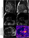
Ischaemic and non-ischaemic heart disease. (A) Late gadolinium enhancement sequence in the 3-chamber view. There is near transmural sub-endocardial enhancement of the mid-apical septum and apex (short arrow, mid-left anterior descending coronary artery territory). A signal void focus is also seen adherent to the apex (arrowhead). This represents a left ventricular thrombus. In addition, there is focal partial thickness sub-endocardial enhancement of basal inferolateral wall (long arrow, circumflex coronary artery territory), which spares the sub-epicardium (denoting an ischaemic etiology). The presence of infarcts in two different coronary territories alludes to the potential presence of multivessel coronary disease. (B) Late gadolinium enhancement sequence demonstrating a ring or circumferential pattern of non-ischaemic enhancement. The areas of enhancement involve the mid-wall or sub-epicardium, sparing the sub-endocardium. (C,D) Stress perfusion scan from a patient with hypertrophic cardiomyopathy. There is widespread circumferential sub-endocardial delayed arrival of contrast (hypoperfusion) at mid-ventricular level (C) and apex (D), typical of microvascular dysfunction. (E,F) Bright blood axis scout at upper abdominal level (E). The normal liver should have signal characteristics similar to the spleen (marked). However, in this patient with hepatic iron overload, the spleen appears almost black due to accelerated dephasing of spins brought about by the increasing field inhomogeneity generated by intrahepatic iron stores. This T2* effect can be used to quantify liver iron levels (F). Here, the liver T2* is ~1.9 ms, denoting moderate hepatic iron overload (normal > 6.3ms) equivalent to ~5–10mg iron/g dry weight.
Figure 5
Figure 5
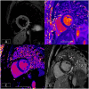
Multiparametric evaluation of a patient with acute myocarditis. (A) Depicts increased T2 signal in the mid-inferior and lateral walls in an epicardial to mid-wall distribution. The absolute T2 time in the inflamed area is increased to ~70 ms (B) whereas the remote myocardium in the septum has a normal T2 time of 45 ms (normal < 55 ms). (C) depicts increased native T1, another marker of tissue injury. This is raised at 1,347 ms in the epicardium of the mid-inferior and lateral walls (normal range: 890–1,035 ms on this platform at 1.5T). (D) illustrates epicardial to mid-wall enhancement of the mid-inferior and lateral walls, which spares the sub-endocardium (typical of myocarditis).
Figure 6
Figure 6
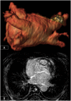
3D-segmentation of the left atrium depicting left atrial anatomy and four pulmonary veins and their tributaries (A). There is extensive fibrosis of the left atrial wall (B) on 3D late enhancement sequences which may reduce the likelihood of successful ablation.
Figure 7
Figure 7
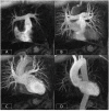
Cardiovascular time resolved 3D-angiography. The bolus of contrast is imaged progressively as it passes from the right side of the heart (A) into the pulmonary arteries (B), left atrium/ventricle (C), and thoracic aorta (D). This obviates the need to precisely time the contrast volume and enables the rapid visualization of different parts of the circulation with a single bolus of contrast.
Figure 8
Figure 8
Well-positioned 4-chamber view (A) demonstrating mitral and tricuspid valves, right and left atria, and ventricles. Incorrect prescription (B) with the slice plane prescribed through the LV OT. Accurate positioning of the 4-chamber view requires the use of three views, the LV VLA view (C), mid-ventricular LV SAX slice (D), and the basal LV SAX slice (E).
Figure 9
Figure 9
Accurate positioning of the basal slice of the LV SAX series requires the use of both the LV VLA (A) and the 4-chamber (B) views to ensure the basal diastolic phase slice is positioned parallel to the mitral valve annulus, avoiding atrium and with an even amount of myocardium around the blood pool (C).
Figure 10
Figure 10
Top row: Positioning corrections for the LV SAX series include repositioning the slice more apically (B) if the basal diastolic phase slice includes atrium (A). If there is an inconsistent amount of myocardium around the blood pool (C), the slice angle is tilted on the LV VLA view (D). Bottom row: A well-positioned RV VLA (E) is achieved by positioning the slice on the 4-chamber view (F) through the RV apex and avoiding the septum, then tilting the slice plane up to the RVOT and pulmonary valve on the basal LV SAX slice (G). The RV SAX series can then be planned on this view to transect the tricuspid valve at an angle between 45° and 90° (H).
Figure 11
Figure 11
Cardiac and respiratory motion monitoring. Motion can either be suppressed (e.g., breath-holding) or monitored with MR navigators or external devices like electrocardiogram (ECG). From the monitored signal, one can extract the respiratory, and cardiac cycles which are needed for triggering (prospective) or gating (retrospective).
Figure 12
Figure 12
Cardiac and respiratory motion handling. Motion can either be suppressed (left column), handled prospectively or retrospectively (middle columns) or corrected/compensated (right column). Different strategies exist to deal with respiratory-only (top), cardiac-only (bottom left), and respiratory and cardiac (bottom right) motion. Prospective triggering: motion can be triggered to shorten the acquisition window to a specific motion state. Retrospective gating: motion is resolved by gating which can be performed exclusively on either respiratory/cardiac motion or on the joint respiratory and cardiac motion (central gating matrix) to yield respiratory/cardiac motion-resolved data. Data between individual gates/motion states can furthermore be compensated by registering them with a rigid or non-rigid motion field along the respiratory or cardiac motion direction.
Figure 13
Figure 13
Fast cardiovascular MR techniques to enable high spatial and/or temporal resolved data acquisition. Cartesian or non-Cartesian undersampling trajectories (left column) can be used to accelerate acquisitions. Depending on the CMR application and acquired trajectory, various image reconstruction techniques (right column) like parallel imaging, compressed sensing, dictionary learning, low-rank, model-based, or more recently deep learning methods can be used. These reconstructions handle and exploit the spatial, temporal, and/or parametric dimensions. In CMR, the forward model, commonly given by k = Ex, maps the unknown (MR signal intensity) image series x to the k-space data k. The forward operator E contains the coil sensitivity maps C (enabling parallel imaging), Fourier operator F and sampling pattern A. If data are undersampled, dynamic images can be estimated using, for e.g., compressed sensing, by minimizing an objective function with a data consistency term (to enforce consistency between the measured data and model prediction) and a regularization term, with sparsifying transform Φ (e.g., spatial wavelet or total variation) and regularization parameter λ. Alternatively, a dictionary learning-based method can learn the sparsifying transform (dictionary, D), and reconstruct the image simultaneously from undersampled k-space data. The low-rank plus sparse (L + S) decomposition model enables the reconstruction of undersampled dynamic k-space data. In this case, the low-rank (L) component captures the temporally correlated background, and the sparse (S) component captures the dynamic information. Model-based reconstruction methods include the physics model in the forward model to directly estimate quantitative parameter maps from fully-sampled or undersampled k-space data.
Figure 14
Figure 14
Schematic overview of the five areas in which Artificial Intelligence (AI)/Machine Learning (ML)/Deep Learning (DL) assisted operations can support the clinical workflow.
Figure 15
Figure 15
Exemplary AI-assisted applications performed on cardiac CINE MRI ranging from acquisition over image reconstruction, analysis, motion to diagnosis. The respective inputs and output data is illustrated.

References

    1. Pohost GM. The history of cardiovascular magnetic resonance. JACC Cardiovasc Imaging. (2008) 1:672–8. 10.1016/j.jcmg.2008.07.009 - DOI - PubMed
    1. Ridgway JP. Cardiovascular magnetic resonance physics for clinicians: part I. J Cardiovasc Magn Reson. (2010) 12:71. 10.1186/1532-429X-12-71 - DOI - PMC - PubMed
    1. Biglands JD, Radjenovic A, Ridgway JP. Cardiovascular magnetic resonance physics for clinicians: part II. J Cardiovasc Magn Reson. (2012) 14:66. 10.1186/1532-429X-14-66 - DOI - PMC - PubMed
    1. Leiner T, Rueckert D, Suinesiaputra A, Baeßler B, Nezafat R, Išgum I, et al. . Machine learning in cardiovascular magnetic resonance: basic concepts and applications. J Cardiovasc Magn Reson. (2019) 21:61. 10.1186/s12968-019-0575-y - DOI - PMC - PubMed
    1. Kramer CM, Barkhausen J, Bucciarelli-Ducci C, Flamm SD, Kim RJ, Nagel E. Standardized cardiovascular magnetic resonance imaging (CMR) protocols: 2020 update. J Cardiovasc Magn Reson. (2020) 22:17. 10.1186/s12968-020-00607-1 - DOI - PMC - PubMed