. 2022 Apr;29(4):376-385.
doi: 10.1038/s41594-022-00742-6. Epub 2022 Mar 21.

DNA is loaded through the 9-1-1 DNA checkpoint clamp in the opposite direction of the PCNA clamp

Affiliations

DNA is loaded through the 9-1-1 DNA checkpoint clamp in the opposite direction of the PCNA clamp

Fengwei Zheng et al. Nat Struct Mol Biol. 2022 Apr.

Abstract

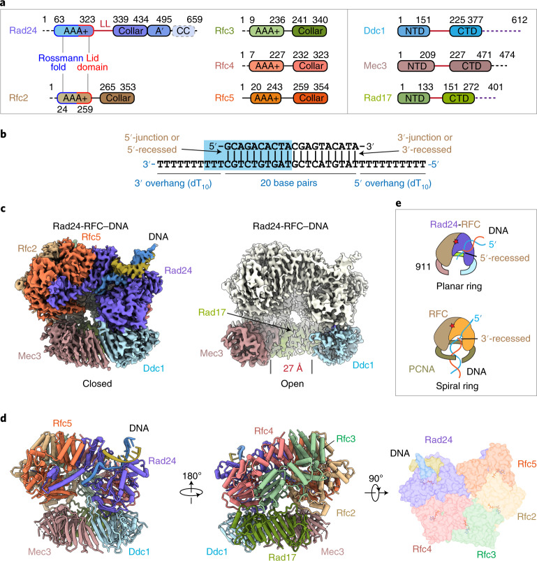
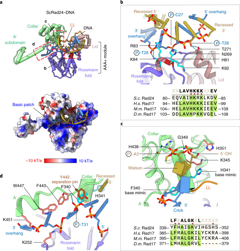
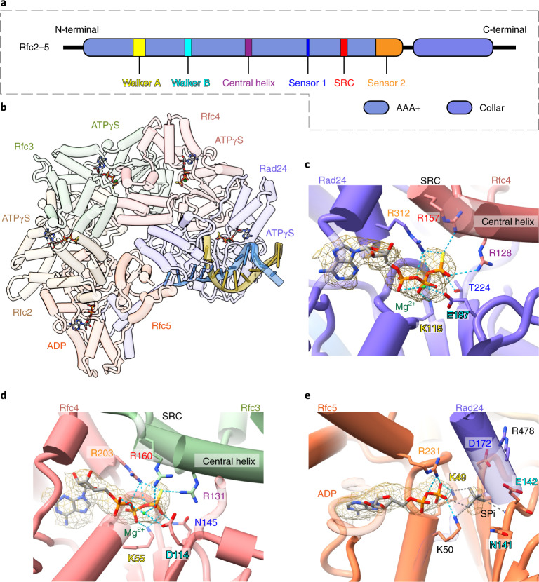
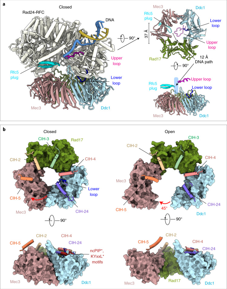
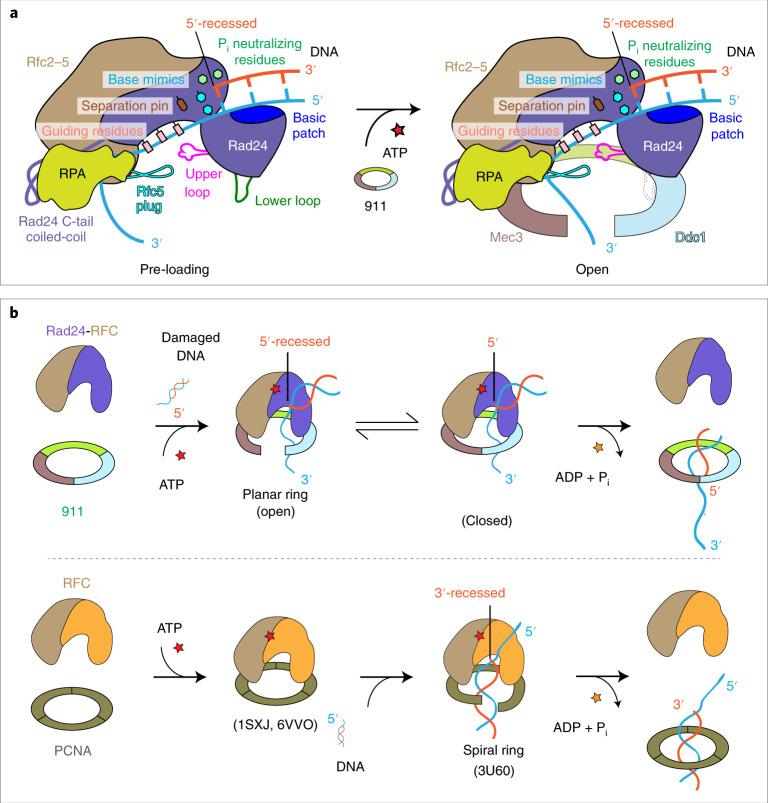
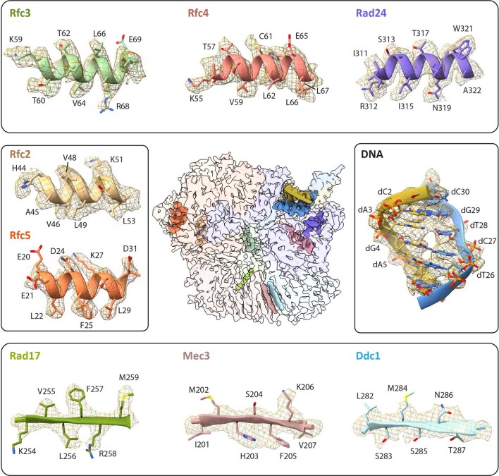
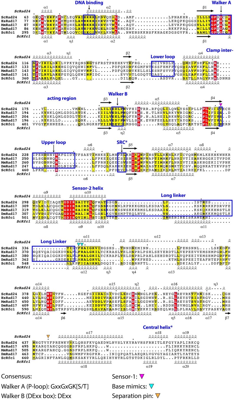
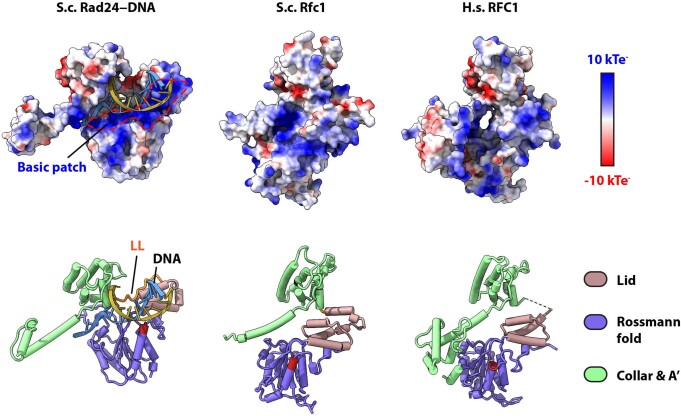
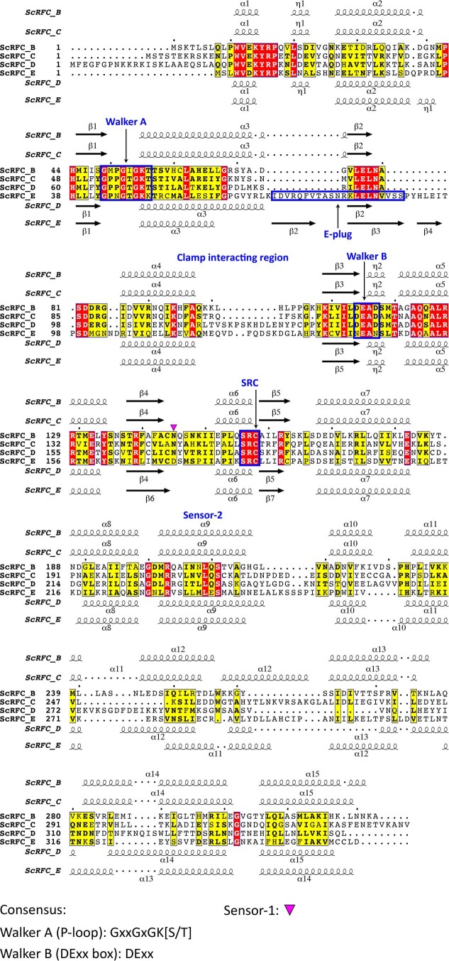
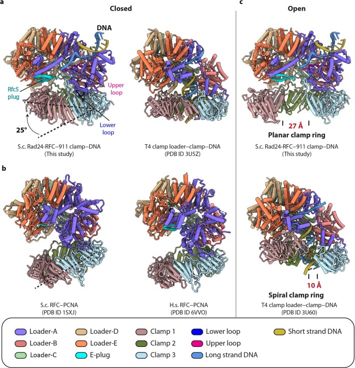
The 9-1-1 DNA checkpoint clamp is loaded onto 5'-recessed DNA to activate the DNA damage checkpoint that arrests the cell cycle. The 9-1-1 clamp is a heterotrimeric ring that is loaded in Saccharomyces cerevisiae by Rad24-RFC (hRAD17-RFC), an alternate clamp loader in which Rad24 replaces Rfc1 in the RFC1-5 clamp loader of proliferating cell nuclear antigen (PCNA). The 9-1-1 clamp loading mechanism has been a mystery, because, unlike RFC, which loads PCNA onto a 3'-recessed junction, Rad24-RFC loads the 9-1-1 ring onto a 5'-recessed DNA junction. Here we report two cryo-EM structures of Rad24-RFC-DNA with a closed or 27-Å open 9-1-1 clamp. The structures reveal a completely unexpected mechanism by which a clamp can be loaded onto DNA. Unlike RFC, which encircles DNA, Rad24 binds 5'-DNA on its surface, not inside the loader, and threads the 3' ssDNA overhang into the 9-1-1 clamp from above the ring.


Conflict of interest statement

The authors declare no competing interests.

Figures

Fig. 1
Fig. 1. Cryo-EM 3D maps of the S.cerevisiae Rad24-RFC–9-1-1–DNA ternary complex.
a, Domain architecture of the eight proteins of the Rad24-RFC–9-1-1 complex: the clamp loader proteins Rad24 and Rfc2–5 and the 9-1-1 clamp proteins Ddc1, Mec3 and Rad17. The C-terminal collar domain forms the tight pentamer connections. The Rad24 A′ domain is associated with the collar domain that is also present in Rfc1, which Rad24 replaces. The unique Rad24 C-terminal coiled coil (CC) is disordered. The dashed lines indicate unsolved regions. LL is the long linker between the Rad24 AAA+ and collar domains. The red lines between the NTDs and CTDs of the 9-1-1 subunits represent the IDCL between the two domains of each 9-1-1 subunit, and the dashed purple lines represent the long C-terminal tails of Ddc1 and Rad17. b, The DNA substrate used to form the ternary complex. Both a 5′- and 3′-recessed DNA junction are present. Nucleotides in the cyan box are resolved in the structure. c, Segmented 3D maps of the Rad24-RFC–9-1-1 clamp–DNA complex in closed (left) and open (right) states. Maps are surface-rendered at 0.1 threshold, except for Ddc1 in the open conformation, which is separately displayed at 0.07 threshold. d, Model of the closed-state complex in front (left) and back (middle) cartoon view and in a top (N-terminal) surface view (right). e, Sketch comparing the DNA binding mode of the Rad24-RFC–9-1-1 (upper panel, this study) with that of the RFC–PCNA, based on the T4 clamp–clamp loader–DNA structure (lower panel; PDB 3U60). Note the drastically different DNA positions and the spiral versus planar clamp rings of the two systems.
Fig. 2
Fig. 2. Rad24 interaction with the 5′-recessed DNA junction.
a, Top: structure of Rad24 bound to the DNA in cartoon view. The 5′-strand is orange and the 3′-strand is cyan. Residues 81-HKRK-84 of the AAA+ domain are in dark red. Areas marked by three dashed red rectangles are shown as close-up views in bd, respectively. Bottom: electrostatic surface view showing a contiguous DNA-binding basic patch on the top of the AAA+ domain. LL: long linker between AAA+ and the collar domains that enables the formation of a large groove to accommodate the DNA. b, Top: interaction between the AAA+ domain and DNA. The four tandem basic residues are shown as cyan sticks. His-81 and Arg-83 insert into the DNA minor groove, and Lys-84 forms two hydrogen bonds with the DNA T28 phosphate of the 3′-strand. Asn-269 of the AAA+ domain and Thr-271 of the AAA+ domain form three hydrogen bonds with the DNA phosphates of C-27 and T-26. Bottom: sequence alignment of the Rad24 four tandem basic residues. S.c., Saccharomyces cerevisiae; H.s., Homo sapiens; M.m., Mus musculus; D.m., Drosophila melanogaster. c, Top: DNA lies on the Rad24 AAA+ domain. Phe-340 and His-341 of the collar domain stabilize the 5′-recessed DNA junction and mimic a nucleotide base to form a hydrophobic stack with the last base pair at the 5′-junction; they each rotate 32° with respect to the interacting base, resembling the 36° rotation of a normal base. His-341, Lys-345 and His-351 surround the 5′-OH of the 5′-strand and prevent a 5′-overhang from binding there. The 5′-OH and the A-3 phosphate form hydrogen bonds with Gly-349 and His-438, respectively. Bottom: sequence alignment of Rad24 base-mimicking residues Phe-340 and His-341, and the 5′-OH blocking Lys-345, His-351. d, Residues guiding 3′-overhang ssDNA into the Rad24-RFC chamber. Tyr-442 is positioned at the 5′-recessed DNA junction resembling a separation pin.
Fig. 3
Fig. 3. Four ATPγS and one ADP are bound to Rad24-RFC.
a, Key ATPase motifs in Rfc2–5. Rad24 lacks the SRC and central helix. b, Top view of Rad24-RFC–DNA in cartoon, omitting the 9-1-1 clamp for clarity. The bound four ATPγSs and one ADP are shown as sticks. ce, Enlarged views of the nucleotide binding pockets in Rad24 (c), Rfc4 (d) and Rfc5 (e). ATPγS binding in Rfc2 and Rfc3 is similar to that in Rfc4 and Rfc3 and is not shown. The residues of the AAA+ module involved in nucleotide binding are the conserved SRC (serine-arginine-cysteine) motif, sensor-1, Walker A (P-loop), Walker B (DExx box), Sensor-2 and the central helix; these are labeled and colored red, orange, yellow, cyan, blue and purple, respectively. The Mg2+ ion is in green. The Rfc5 nucleotide pocket is occupied by ADP. Because Rad24 lacks the SRC motif, there is only one arginine (Arg-478) at the Rfc5:Rad24 interface, which points away from the nucleotide due to the absence of the γ-phosphate. The isolated strong density (displayed at 6σ) next to ADP is modeled as a thiophosphate (SPi) and is shown in gray sticks. The phosphate is coordinated by both Lys-49 and Lys-50 of the Walker A motif as well as the backbone nitrogen of Glu-142 in the Walker B motif. For clarity, only the hydrogen bonds with the nucleotide phosphates are shown.
Fig. 4
Fig. 4. Interaction between Rad24-RFC and the 9-1-1 clamp in the closed and open states.
a, Tilted, bottom and side views of the closed 9-1-1 clamp, highlighting the positions of three important loops. The upper insertion loop of Rad24 and the Rfc5 plug narrow the interior chamber of Rad24-RFC to 12 Å, suitable for ssDNA but excluding dsDNA binding. The Rad24 lower insertion loop binds Ddc1 of the 9-1-1 clamp to control the ring opening/closure. The inner diameter of 9-1-1 is 37 Å. b, Comparison of the closed and open 9-1-1 clamp in top and side surface views. Superimposed on the clamps (in surface view) are the CIH and connecting loop of each loader subunit, shown in cartoon view. The non-canonical PIP (ncPIP) motif and the KYxxL-like motif at the end of the Rad24 CIH are labeled and highlighted in dark red. The Rad24 lower loop bound to Ddc1 is ordered in the closed state but becomes disordered and loses contact with Ddc1 in the open state, leading to a 45° in-plane rotation of Mec3 to form the DNA entry gate.
Fig. 5
Fig. 5. The mechanism of 9-1-1 loading onto the 5′-recessed DNA junction by Rad24-RFC.
a, Rad24 confers the 5′-recessed DNA junction with specificity via several unique structural features: the long linker between the collar and AAA+ domains, enabling their separation and the formation of the dsDNA binding groove; the basic patch on top of the AAA+ domain that binds dsDNA; the 5′-phosphate neutralizing residues, the base mimics, the separation pin that facilitates binding to the 5′-junction; and the Rad24 upper loop and the Rfc5 plug, which limit the chamber size and prevent dsDNA from entering the loader chamber. RPA binds to the C-terminal coiled coil of Rad24, thereby holding the ssDNA of the 5′-recessed DNA junction away from the space below the Rad24-RFC where the 9-1-1 clamp will bind. This is a bipartite DNA binding mechanism that we propose facilitates 9-1-1 clamp recruitment and loading onto ssDNA at a 5′ DNA junction. The loaded 9-1-1 clamp could then diffuse from ssDNA onto the dsDNA. b, Upper panel: the loading steps of the 9-1-1 clamp by Rad24-RFC. Both open and closed states are observed in this study. Lower panel: the loading steps of PCNA by RFC based on previous structural studies. In addition to the opposite DNA binding mode, the inner chamber of RFC is a spiral that is molded by the binding of DNA, whereas Rad24-RFC does not adopt a spiral structure as the dsDNA region is solely bound by the Rad24 subunit and does not enter the inner chamber of Rad24-RFC. See main text for details. PDB codes for the structures are indicated (1SXJ, 6VVO and 3U60).
Extended Data Fig. 1
Extended Data Fig. 1. Assembly of the Rad24-RFC–9-1-1–DNA ternary complexes.
a) SDS-PAGE gels of purified Rad24-RFC and the 9-1-1 clamp. Similar gels were run >3 times. b) A raw micrograph of the mixture of Rad24-RFC with 9-1-1 and a 3′-recessed DNA substrate after incubation in an ice-water bath for 3 hr. 12,000 similar micrographs were recorded. c) 2D class averages. No ternary complex of Rad24-RFC–9-1-1–DNA was observed. Only the separate 9-1-1 ring and the Rad24-RFC particles were observed. d) A typical raw micrograph of the mixture of Rad24-RFC with 9-1-1 and a double-tailed DNA substrate containing both the 5′- and 3′- recessed DNA junctions. 14521 similar micrographs were recorded. e) Selected 2D class averages with different views, revealing the presence of the targeted Rad24-RFC–9-1-1 clamp–DNA ternary complexes. Scale bars are shown in the lower right corner in each panel. Source data
Extended Data Fig. 2
Extended Data Fig. 2. Workflow of image processing and 3D reconstruction.
CryoSPARC Live is used to monitor data collection and real-time data processing. We used the particle picking program Topaz and ‘Build and Retrieve’ to obtain particles in more views. 3D variability analysis was applied to yield the 3.2-Å resolution 3D maps in the closed and open states of the Rad24-RFC–9-1-1 clamp–DNA complex.
Extended Data Fig. 3
Extended Data Fig. 3. Resolution estimations of the closed (a) and open (b) states of the Rad24-RFC–9-1-1–DNA complex.
Upper panels, the two 3D maps colored by local resolution. The dimensions of the structures are labeled. Middle panels, the 0.143 criterion of the gold standard Fourier shell correlation (GSFSC) was used to estimate the average resolutions. Bottom panels, the directional anisotropy of the two maps as quantified by the 3D-FSC server (https://3dfsc.salk.edu/). The sphericity of closed and open state is 0.949 and 0.923, respectively, demonstrating good anisotropic property of both maps.
Extended Data Fig. 4
Extended Data Fig. 4. Fitting of the atomic model with the EM density in selected regions of the Rad24-RFC–9-1-1 clamp–DNA complex 3D maps.
The central panel shows the segmented 3D map in 90% transparent surface view, except for the nine selected regions shown in solid surface. The nine selected regions – one from each component of the ternary complex – are shown in peripheral panels, with the atomic model in cartoon and residues in sticks, and with the EM density shown in wire meshes. For a fuller representation, the selected upper regions (Rad24-RFC–DNA) used the EM map in the open state, and the selected lower 9-1-1 clamp regions are from the EM map in the closed state.
Extended Data Fig. 5
Extended Data Fig. 5. Sequence alignment of yeast Rad24, metazoan RAD17 and yeast Rfc1.
Helices and β-strands are shown as coils and arrows, respectively. The assignments are produced by ESPript 3.0 (https://espript.ibcp.fr/ESPript/ESPript/) based on the structures S.c. Rad24 (this study) and S.c. Rfc1 (PDB code 1SXJ). The flashy color scheme was applied. Key features are marked above the sequences. Note that the linker region between collar and AAA+ module of Rfc1 contains only one residue (L549) and is not included in the box. The SRC (serine-arginine-cysteine) motif – conserved in Rfc2–5 – is absent in Rad24/RAD17 and Rfc1/RFC1; its location corresponding to the SRC motif in Rfc2–5 is boxed and labeled as SRC*.
Extended Data Fig. 6
Extended Data Fig. 6. Structural comparison of Rad24 and Rfc1/RFC1.
Upper panel, the electrostatic potential charge surface of the S.c. Rad24 (this study), S.c. Rfc1 (PDB code 1SXJ), and human RFC1 (PDB code 6VVO). In Rad24, a contiguous basic patch on top of the AAA+ domain enables DNA binding. Rfc1/RFC1 lack such contiguous basic path. Lower panel, the corresponding atomic models shown in cartoons. These structures are aligned based on the full loader complexes to achieve the best superposition. The four tandem basic residues in Rad24 and the corresponding region in Rfc1/RFC1 are highlighted in firebrick. Note that the lid and Rossmann fold domains move away from the collar domain plus the associated A’ domain by a 35-Å shift and a 20º rotation, creating a large groove for dsDNA binding.
Extended Data Fig. 7
Extended Data Fig. 7. Structure-based sequence alignment of S.c. Rfc2–5.
Structural elements of Rfc3 and 4 are shown above and that of Rfc2 and 5 are shown below the sequences. Assignment of the secondary structural elements also considered both the Rad24-RFC structure (current study) and the S.c. RFC structure (PDB code 1SXJ).
Extended Data Fig. 8
Extended Data Fig. 8. Comparison of the available structures of the DNA clamp–clamp loader–(DNA) complexes.
a) Structure of the yeast Rad24-RFC bound to 9-1-1 and DNA compared with the T4 phage clamp loader–clamp bound to a DNA substrate. b) Comparison of the yeast RFC–PCNA (PDB code 1SXJ) with the human RFC–PCNA (PDB code 6VVO), all in a clamp ring closed configuration. The Rad24-RFC–9-1-1 clamp is more compact than the yeast and human RFC–PCNA structures, with the 9-1-1 ring tilting 25° toward the Rad24-RFC loader. c) Structure comparison of the Rad24-RFC–9-1-1 clamp–DNA with the T4 clamp–clamp loader–DNA (PDB code 3U60), both in the open clamp ring conformation. Note the 27-Å DNA gate in the planar 9-1-1 clamp with the 10-Å DNA gate in the T4 spiral clamp. To facilitate comparison, the loader subunits are labeled A through E according to their physical location in the complex.

Similar articles

Cited by

References

    1. Sancar A, Lindsey-Boltz LA, Unsal-Kacmaz K, Linn S. Molecular mechanisms of mammalian DNA repair and the DNA damage checkpoints. Annu. Rev. Biochem. 2004;73:39–85. doi: 10.1146/annurev.biochem.73.011303.073723. - DOI - PubMed
    1. Harrison JC, Haber JE. Surviving the breakup: the DNA damage checkpoint. Annu. Rev. Genet. 2006;40:209–235. doi: 10.1146/annurev.genet.40.051206.105231. - DOI - PubMed
    1. Su TT. Cellular responses to DNA damage: one signal, multiple choices. Annu. Rev. Genet. 2006;40:187–208. doi: 10.1146/annurev.genet.40.110405.090428. - DOI - PubMed
    1. Zhou BB, Elledge SJ. The DNA damage response: putting checkpoints in perspective. Nature. 2000;408:433–439. doi: 10.1038/35044005. - DOI - PubMed
    1. Abraham RT. Cell cycle checkpoint signaling through the ATM and ATR kinases. Genes Dev. 2001;15:2177–2196. doi: 10.1101/gad.914401. - DOI - PubMed

Publication types

MeSH terms

Substances

LinkOut - more resources