

Resistor-free and one-board-fits-all ratio adjustable power splitter for add-on RF shimming in high field MRI
- PMID: 35316747
- PMCID: PMC9050946
- DOI: 10.1016/j.jmr.2022.107194
Resistor-free and one-board-fits-all ratio adjustable power splitter for add-on RF shimming in high field MRI
Abstract
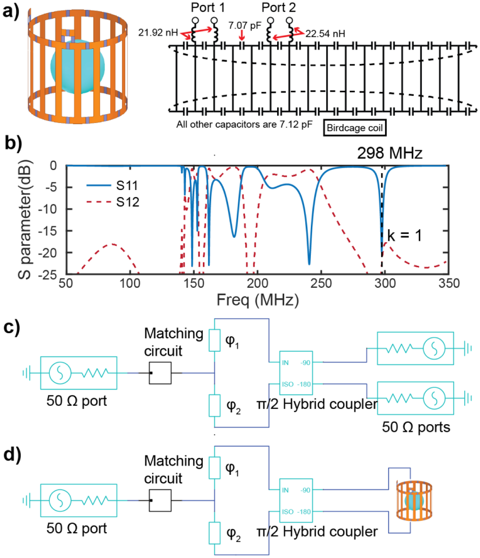
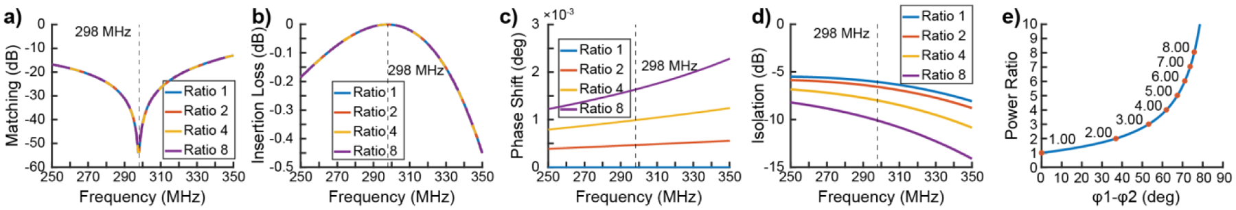
Ratio adjustable power splitter (RAPS) circuits were recently proposed for add-on RF shimming. Previous RAPSs split the input RF signal with a Wilkinson splitter or 50-Ω-terminated hybrid coupler into two branches, delay these two signals with cable/microstrip line phase shifters, and recombine them with another hybrid coupler. They require resistors to provide high output isolation and a cable/microstrip line library to realize desired splitting ratios. Here we propose a novel resistor-free RAPS circuit in which the Wilkinson splitter/50-Ω-terminated hybrid is replaced with a resistor-free T-junction splitter. A novel sliding mechanism was employed to further combine the T-junction's output arms with subsequent phase shifters and realize a one-board-fits-all design. The resistor-free RAPS was theoretically analyzed, simulated, and validated on workbench and MRI experiments. The resistor-free RAPS's splitting ratio has a tan/cot dependence on the phase/length difference between the T-junction output arms. The ratio can be continuously adjusted to any value by sliding the input arm without additional cable/microstrip libraries, largely saving time and effort when determining the best RF weights in practice. The fabricated resistor-free RAPS has a compact size, excellent input impedance matching, and a low insertion loss. Potential safety concerns caused by unwanted power dissipation on RF resistors are eliminated. The simulation and MRI experiments demonstrated that the resistor-free RAPS functions well on a widely-used Tx coil.
Keywords: One-board-fits-all; Power splitter; RF shimming; Resistor-free; Ultrahigh field.
Copyright © 2022 Elsevier Inc. All rights reserved.
Conflict of interest statement
Declaration of Competing Interest The authors declare that they have no known competing financial interests or personal relationships that could have appeared to influence the work reported in this paper.
Figures


Similar articles
-
Hybrid-pair ratio adjustable power splitters for add-on RF shimming and array-compressed parallel transmission.Magn Reson Med. 2021 Dec;86(6):3382-3390. doi: 10.1002/mrm.28934. Epub 2021 Jul 19. Magn Reson Med. 2021. PMID: 34286860 Free PMC article.
-
On the design and manufacturing of miniaturized microstripline power splitters for driving multicoil transmit arrays with arbitrary ratios at 7 T.NMR Biomed. 2022 Nov;35(11):e4793. doi: 10.1002/nbm.4793. Epub 2022 Aug 1. NMR Biomed. 2022. PMID: 35772938 Free PMC article.
-
Ratio-adjustable power splitters for array-compressed parallel transmission.Magn Reson Med. 2018 Apr;79(4):2422-2431. doi: 10.1002/mrm.26847. Epub 2017 Jul 31. Magn Reson Med. 2018. PMID: 28758248 Free PMC article.
-
A Compact, High Power Capable, and Tunable High Directivity Microstrip Coupler.IEEE Trans Microw Theory Tech. 2016 Oct;64(10):3217-3223. doi: 10.1109/TMTT.2016.2602835. Epub 2016 Sep 12. IEEE Trans Microw Theory Tech. 2016. PMID: 28303035 Free PMC article.
-
Robust RF shimming and small-tip-angle multispoke pulse design with finite-difference regularization.Magn Reson Med. 2021 Sep;86(3):1472-1481. doi: 10.1002/mrm.28820. Epub 2021 May 1. Magn Reson Med. 2021. PMID: 33934406
Cited by
-
A Review of Current Control and Decoupling Methods for MRI Transmit Arrays.IEEE Rev Biomed Eng. 2025;18:388-400. doi: 10.1109/RBME.2024.3351713. Epub 2025 Jan 28. IEEE Rev Biomed Eng. 2025. PMID: 38194402 Free PMC article. Review.
-
Subwavelength dielectric waveguide for efficient travelling-wave magnetic resonance imaging.Nat Commun. 2024 Mar 14;15(1):2298. doi: 10.1038/s41467-024-46638-5. Nat Commun. 2024. PMID: 38485742 Free PMC article.
References
-
- Umutlu L, Ladd ME, Forsting M, Lauenstein T, 7 Tesla MR imaging. Opportunities and challenges, RoeFo - Fortschritte Auf Dem Gebiete Der Roentgenstrahlen Und Der Bildgebenden Verfahren. 186 (2014). https://www.osti.gov/etdeweb/biblio/22208869 (accessed October 8, 2021). - PubMed
-
- Abduljalil AM, Kangarlu A, Zhang X, Burgess RE, Robitaille P-ML, Acquisition of Human Multislice MR Images at 8 Tesla, Journal of Computer Assisted Tomography. 23 (1999) 335–340. - PubMed
Publication types
MeSH terms
Grants and funding
LinkOut - more resources
Full Text Sources
Other Literature Sources
Medical
Miscellaneous
