

The Effect of Heat Source Path on Thermal Evolution during Electro-Gas Welding of Thick Steel Plates
- PMID: 35329667
- PMCID: PMC8949234
- DOI: 10.3390/ma15062215
The Effect of Heat Source Path on Thermal Evolution during Electro-Gas Welding of Thick Steel Plates
Abstract
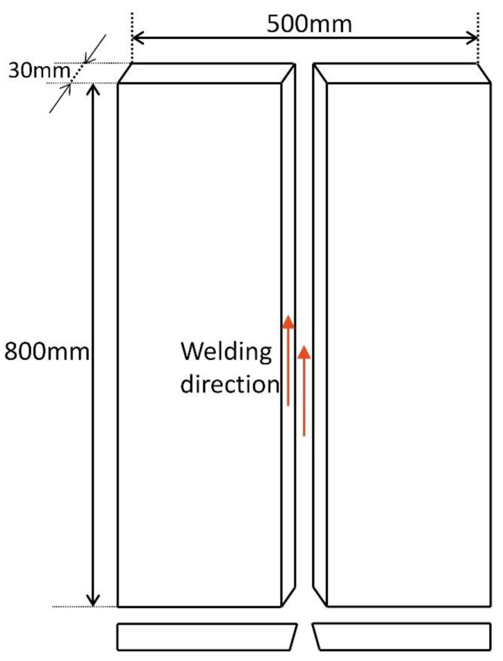
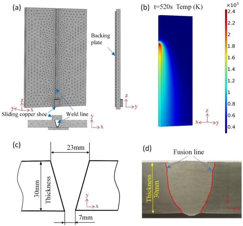
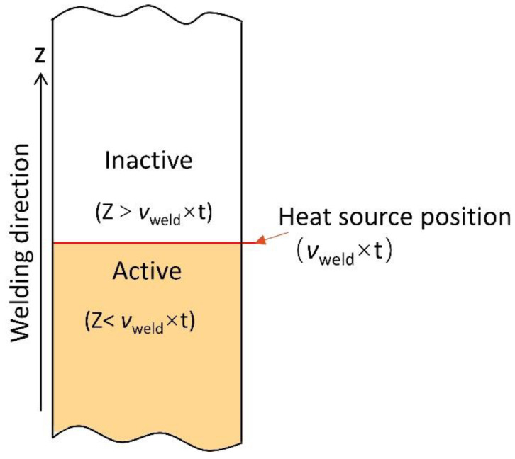
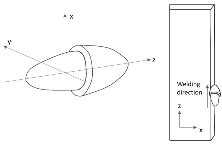
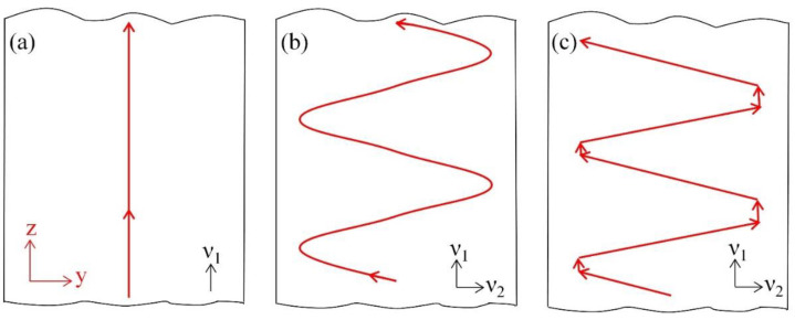
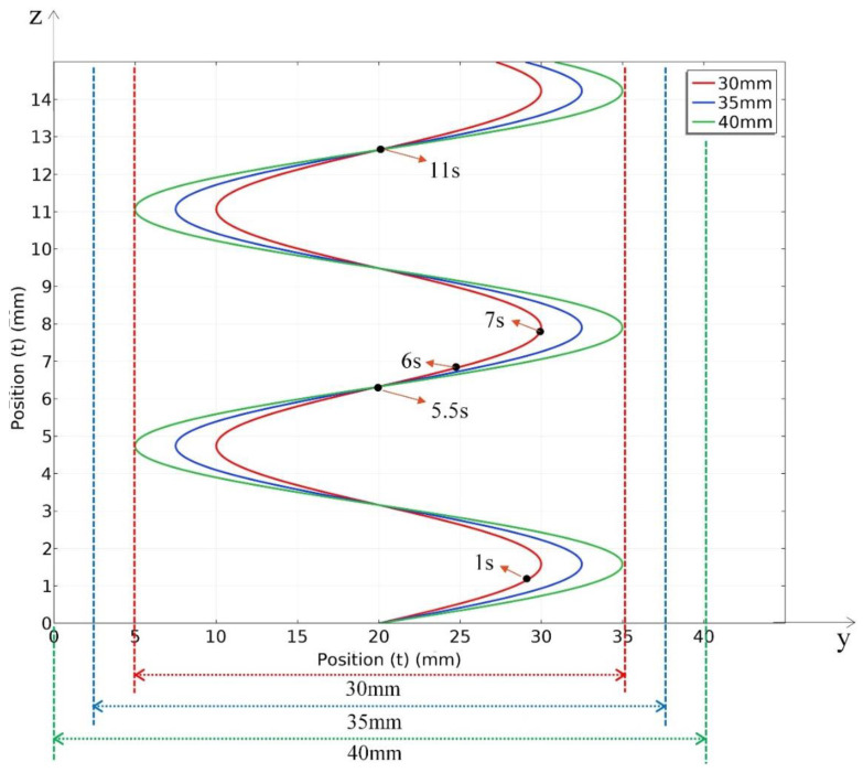
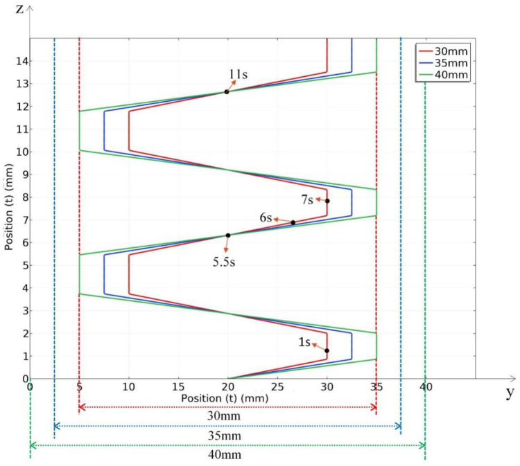
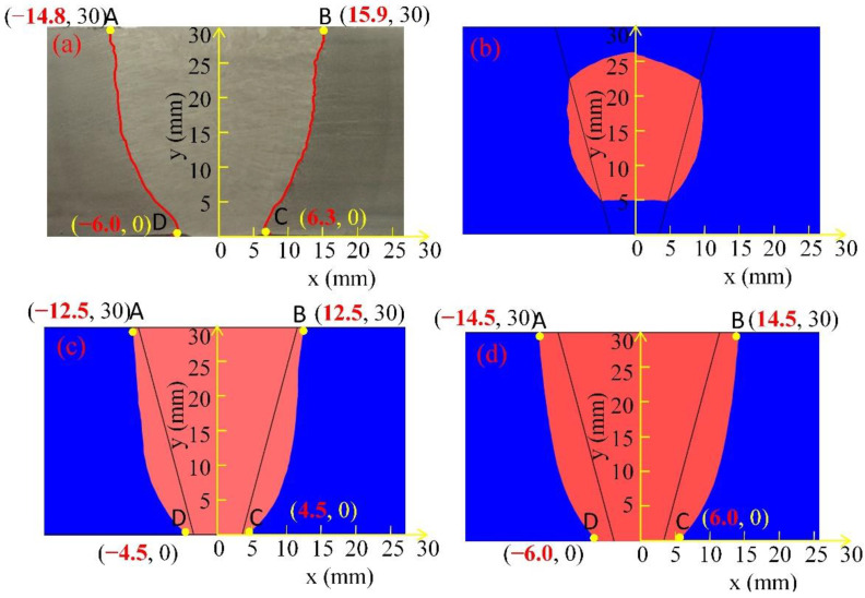
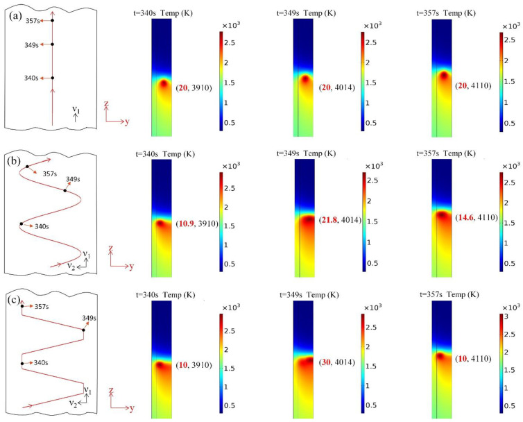
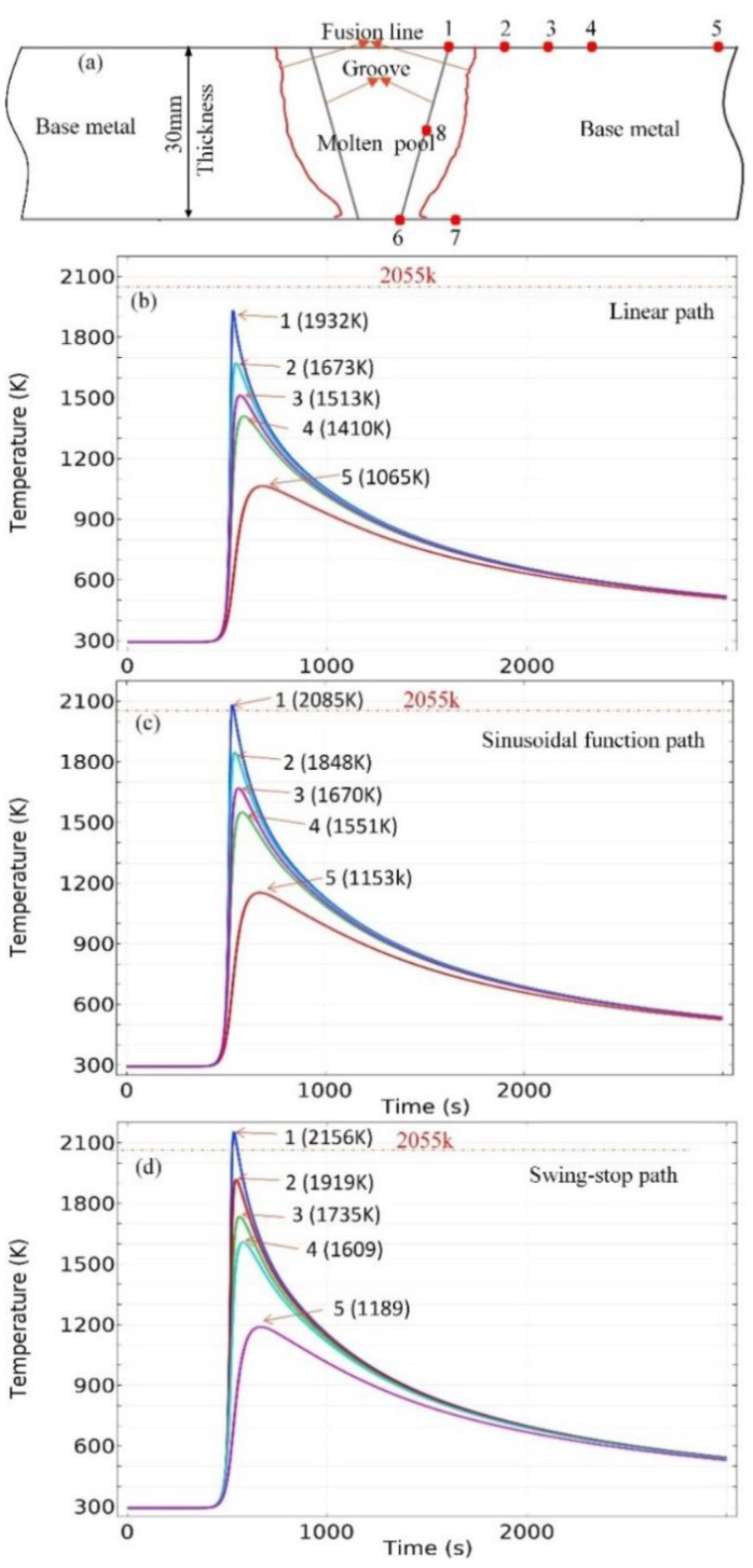
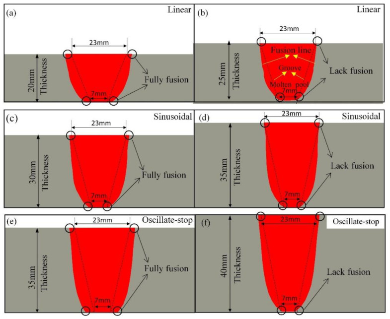
In recent years, the shipbuilding industry has experienced a growing demand for tighter control and higher strength requirements in thick steel plate welding. Electro-gas welding (EGW) is a high heat input welding method, widely used to improve the welding efficiency of thick plates. Modelling the EGW process of thick steel plates has been challenging due to difficulties in accurately depicting the heat source path movement. An EGW experiment on 30 mm thickness E36 steel plates was conducted in this study. A semi-ellipsoid heat source model was implemented, and its movement was mathematically expressed using linear, sinusoidal, or oscillate-stop paths. The geometry of welding joints, process variables, and steel composition are taken from industrial scale experiments. The resulting thermal evolutions across all heat source-path approaches were verified against experimental observations. Practical industrial recommendations are provided and discussed in terms of the fusion quality for E36 steel plates with a heat input of 157 kJ/cm. It was found that the oscillate-stop heat path predicts thermal profile more accurately than the sinusoidal function and linear heat path for EGW welding of 30 mm thickness and above. The linear heat path approach is recommended for E36 steel plate thickness up to 20 mm, whereas maximum thickness up to 30 mm is appropriate for sinusoidal path, and maximum thickness up to 35 mm is appropriate for oscillate-stop path in EGW welding, assuming constant heat input.
Keywords: electro-gas welding; finite element analysis; heat source movement path; high heat input; thermal evolution.
Conflict of interest statement
The authors declare no conflict of interest.
Figures

References
-
- Ichimiya K., Sumi H., Hirai T. 460 MPa Yield Strength Class Steel Plate with JFE EWEL® Technology for Large Heat Input Welding. JFE Tech. Rep. 2008;5:7–12.
-
- Kaplan M.B., Solomon S. A coming boom in commercial shipping? The potential for rapid growth of noise from commercial ships by 2030. Mar. Policy. 2016;73:119–121. doi: 10.1016/j.marpol.2016.07.024. - DOI
-
- Sasaki K., Suda K., Motomatsu R.I., Hashiba Y., Ohkita S., Imai S. Development of Two-electrode Electro-gas Arc Welding Process. Shinnittetsu Giho. 2004;90:57–64.
-
- Fritzsche A., Avilov V., Gumenyuk A., Hilgenberg K., Rethmeier M. High power laser beam welding of thick-walled ferromagnetic steels with electromagnetic weld pool support. Phys. Procedia. 2016;83:362–372. doi: 10.1016/j.phpro.2016.08.038. - DOI
-
- Wang G., Li J.B., Sha Y.Z., Ma J. Study on the penetration of electrogas welding. Weld. Technol. 2002;5:8–9.
Grants and funding
LinkOut - more resources
Full Text Sources
