. 2022 Mar 9;14(6):1092.
doi: 10.3390/polym14061092.

Conductive Plastics from Al Platelets in a PBT-PET Polyester Blend Having Co-Continuous Morphology

Affiliations

Conductive Plastics from Al Platelets in a PBT-PET Polyester Blend Having Co-Continuous Morphology

Abdullah Alhamidi et al. Polymers (Basel). .

Abstract

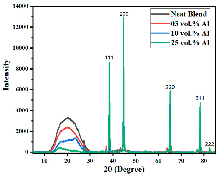
Conductive plastics are made by placing conductive fillers in polymer matrices. It is known that a conductive filler in a binary polymer blend with a co-continuous morphology is more effective than in a single polymer, because it aids the formation of a 'segregated conductive network'. We embedded a relatively low-cost conductive filler, aluminium nano platelets, in a 60/40 PBT/PET polymer blend. While 25 vol.% of the Al nanoplatelets when placed in a single polymer (PET) gave a material with the resistivity of an insulator (1014 Ωcm), the same Al nano platelets in the 60/40 PBT/PET blend reduced the resistivity to 7.2 × 10⁷ Ωcm, which is in the category of an electrostatic charge dissipation material. While PET tends to give amorphous articles, the 60/40 PBT/PET blends crystallised in the time scale of the injection moulding and hence the conductive articles had dimensional stability above the Tg of PET.

Keywords: PET/PBT blend; conductive plastics; mechanical properties; metal–plastics; reinforced polymer composite.


Conflict of interest statement

The authors declare no conflict of interest.

Figures

Figure 1
Figure 1
Schematic diagram of the composite preparation process.
Figure 2
Figure 2
SEM image of Al nano platelet particles.
Figure 3
Figure 3
Injection-moulded tensile bar appearance of polymers and composites. From top to bottom: amorphous PET bar is transparent; semi-crystalline PBT bar is white; 60/40 PBT/PET bar is cream tinted; and the Al nano platelet-filled 60/40 PBT/PET bar is silvery.
Figure 4
Figure 4
Cross-section of the 60/40 PBT/PET bar shows a transparent jacket. The horizontal width of the bar is 12.7 mm.
Figure 5
Figure 5
Wide-angle X-ray diffractograms for bars of Al nano platelet 60/40 PBT/PET composites showing the polymer and Al peaks. The polymer blend shows an amorphous halo in the skin portion of the bar. The intense peaks with the Miller indices are from the aluminium. Note, however, that the small sharp peaks at 2θ ~27°, 37°, 44°, 64°, and 77° are artefacts from the sample holder.
Figure 6
Figure 6
(a) DSC of the shaved skins of 60/40 PBT/PET and Al-60/40 PBT/PET bars shows a cold crystallisation exothermic peak at ~60 °C after the Tg, at ~50 °C, during heating. It indicates there is an amorphous skin in all of them; the arrow indicates the exothermic cold crystallisation during the scan. (b) DSC of 60/40 PBT/PET and Al-60/40 PBT/PET (core of moulded bars after shaving off the skin) shows no cold crystallization after the Tg. This indicates the polymers in the core of the bars had crystallized during moulding.
Figure 7
Figure 7
Electrical resistivity of 60/40 PBT/PET blend and Al nano platelet-filled 60/40 PBT/PET. The percolation threshold with Al nano platelets is 20–25 vol.%.
Figure 8
Figure 8
The thermal conductivity of Al nano platelet composites, at room temperature.
Figure 9
Figure 9
From the left, transparent amorphous PET bar; PET bar after annealing at 150 °C for 30 min. It cold crystallises, turns white, but shrinks and warps; as-moulded 60/40 PBT/PET bar is turbid and has a yellow tint, and shows a transparent amorphous skin; after annealing 60/40 PBT/PET bar at 150 °C for 30 min, the skin cold crystallises, but unlike the amorphous PET, there is no major shrinkage or warpage.
Figure 10
Figure 10
(a) The tensile modulus of 60/40 PBT/PET filled with aluminium nano platelets. (b) The tensile strength of 60/40 PBT/PET filled with aluminium nano platelets. (c) The strain at break of 60/40 PBT/PET filled with aluminium nano platelets.
Figure 11
Figure 11
(a) Flexural modulus of 60/40 PBT/PET filled with aluminium nano platelets. (b) The flexural strength of 60/40 PBT/PET filled with aluminium nano platelets.
Figure 11
Figure 11
(a) Flexural modulus of 60/40 PBT/PET filled with aluminium nano platelets. (b) The flexural strength of 60/40 PBT/PET filled with aluminium nano platelets.
Figure 12
Figure 12
The impact resistance of 60/40 PBT/PET filled with aluminium nano platelets.
Figure 13
Figure 13
A 60/40 PBT/PET melt emerging from the die is transparent, indicating that the components are either miscible in the melt, or the constituents are in nano domains with similar refractive indices. On cooling, whitening occurs due to crystallisation.
Figure 14
Figure 14
(a) Low magnification picture of cryo-fracture surface of 60/40 PBT/PET bar. The white size bar = 100 μm. (b) High magnification of the cryo-fracture surface of 60/40 PBT/PET bar shows the interpenetrating co-continuous domains of PET and PBT. The white size bar = 1 μm. Unlike most other polymer blends, the domain dimensions are sub-micron.
Figure 15
Figure 15
(a) SEM image of the cryo-fracture surface of a bar of the 60/40 PBT/PET blend with 10 vol.% Al flakes. The platelets are seen edgewise. The rectangle in the left corner is the cross-section of the bar (not to scale) and is placed to visualise the platelet orientation relative to the bar. The arrow shows polymer coating on a platelet. Dotted arrow shows a folded platelet. The white size bar = 10 μm. (b) SEM image of the cryo-fracture surface of a bar of the 60/40 PBT/PET blend with 25 vol.% of Al nano platelets. The platelets are seen edgewise. The arrow shows a folded platelet with polymer coating. The white size bar = 10 μm.
Figure 15
Figure 15
(a) SEM image of the cryo-fracture surface of a bar of the 60/40 PBT/PET blend with 10 vol.% Al flakes. The platelets are seen edgewise. The rectangle in the left corner is the cross-section of the bar (not to scale) and is placed to visualise the platelet orientation relative to the bar. The arrow shows polymer coating on a platelet. Dotted arrow shows a folded platelet. The white size bar = 10 μm. (b) SEM image of the cryo-fracture surface of a bar of the 60/40 PBT/PET blend with 25 vol.% of Al nano platelets. The platelets are seen edgewise. The arrow shows a folded platelet with polymer coating. The white size bar = 10 μm.

References

    1. Alemour B., Badran O., Hassan M.R. A review of using conductive composite materials in solving lightening strike and ice accumulation problems in aviation. J. Aerosp. Technol. Manag. 2019;11 doi: 10.5028/jatm.v11.1022. - DOI
    1. Huang J.C. Carbon black filled conducting polymers and polymer blends. Adv. Polym. Technol. J. Polym. Process. Inst. 2002;21:299–313. doi: 10.1002/adv.10025. - DOI
    1. Nakamura S., Saito K., Sawa G., Kitagawa K. Percolation threshold of carbon black-polyethylene composites. Jpn. J. Appl. Phys. 1997;36:5163. doi: 10.1143/JJAP.36.5163. - DOI
    1. Ren D., Zheng S., Wu F., Yang W., Liu Z., Yang M. Formation and evolution of the carbon black network in polyethylene/carbon black composites: Rheology and conductivity properties. J. Appl. Polym. Sci. 2014;131 doi: 10.1002/app.39953. - DOI
    1. Bhattacharya S., Chaklader A. Review on metal-filled plastics. Part 1. Electrical conductivity. Polym.-Plast. Technol. Eng. 1982;19:21–51. doi: 10.1080/03602558208067726. - DOI

LinkOut - more resources