Review
. 2022 Feb 28;14(3):543.
doi: 10.3390/pharmaceutics14030543.

Methods of Liposomes Preparation: Formation and Control Factors of Versatile Nanocarriers for Biomedical and Nanomedicine Application

Affiliations
Review

Methods of Liposomes Preparation: Formation and Control Factors of Versatile Nanocarriers for Biomedical and Nanomedicine Application

Domenico Lombardo et al. Pharmaceutics. .

Abstract

Liposomes are nano-sized spherical vesicles composed of an aqueous core surrounded by one (or more) phospholipid bilayer shells. Owing to their high biocompatibility, chemical composition variability, and ease of preparation, as well as their large variety of structural properties, liposomes have been employed in a large variety of nanomedicine and biomedical applications, including nanocarriers for drug delivery, in nutraceutical fields, for immunoassays, clinical diagnostics, tissue engineering, and theranostics formulations. Particularly important is the role of liposomes in drug-delivery applications, as they improve the performance of the encapsulated drugs, reducing side effects and toxicity by enhancing its in vitro- and in vivo-controlled delivery and activity. These applications stimulated a great effort for the scale-up of the formation processes in view of suitable industrial development. Despite the improvements of conventional approaches and the development of novel routes of liposome preparation, their intrinsic sensitivity to mechanical and chemical actions is responsible for some critical issues connected with a limited colloidal stability and reduced entrapment efficiency of cargo molecules. This article analyzes the main features of the formation and fabrication techniques of liposome nanocarriers, with a special focus on the structure, parameters, and the critical factors that influence the development of a suitable and stable formulation. Recent developments and new methods for liposome preparation are also discussed, with the objective of updating the reader and providing future directions for research and development.

Keywords: drug delivery; lipid-based nanocarriers; liposome formation; nanomedicine; phospholipids self-assembly.


Conflict of interest statement

The authors declare no conflict of interest.

Figures

Figure 1
Figure 1
Schematic representation a DMPC unilamellar liposome (A). Typical onion-like structure composed of concentric bilayer surfaces (hydrated multilayers) of a multilamellar vesicle (MLV) (B). Characteristic phases of a water solution of DMPC phospholipids (C).
Figure 2
Figure 2
Schematic representation of the main interactions exhibited by liposomes (A). Main structural characteristics of the anticancer drug Doxil (B).
Figure 3
Figure 3
Schematic representation of the main stages of the thin-film hydration method of liposome preparation. The main lipid components (and eventually lipophilic drugs/macromolecules) are dissolved in organic solvent (A). After the evaporation of the solvent, a dry (thin) lipid film is formed (B). The lipid film is then rehydrated in a saline buffer (eventually containing hydrophilic dugs to be entrapped), causing a swelling of the lipid bilayers’ stacks (C). The successive agitation/stirring of the sample favors the formation of (polydispersed) multilamellar vesicles (D). The final stages of the production process include the liposomes’ downsizing (E), purification (F), and characterization (G).
Figure 4
Figure 4
Self-assembly process in mixtures of lipids and detergents. (A) Membrane solubilization and reconstitution by addition (or removal) of detergents. (B) Characteristic molecular geometries’ and aggregates’ structures of (pure) lipids and detergents. (CF) Main stages of the detergent removal method. Initially, the lipid hydration with a detergent solution allows for the formation of mixed (detergent/lipids) micelles (C). The successive dilution of mixed micellar solution with aqueous buffer favors an increase of the mixed micelles’ size (and polydispersity) (D), followed by a transition to the vesicles’ structures (E). The formation process is completed by a complementary method for the removal of the residual detergent inside the liposomal nanoformulation (F).
Figure 5
Figure 5
Schematic representation of the main stages of the ethanol injection method. A composition of lipids dissolved in alcohol solution is injected into an aqueous phase (buffer) (A). The dilution of ethanol in the water solution favors the self-assembly of lipid components and the formation of bilayer planar fragments (B). Finally, the ethanol evaporation (depletion) favors the fusion of the lipids’ fragments and the formation of closed unilamellar vesicles (SUL and LUV) (C).
Figure 6
Figure 6
Schematic representation of the main stages of the reverse-phase evaporation method. Lipids are dissolved in organic solvent (A), and the formation of inverted micelles is observed (B). The addition of aqueous media (buffer), followed by emulsification of the solution, favors the formation a homogeneous dispersion of a W/O microemulsion (C). With the final elimination of the organic solvent (by using rotary evaporation, under vacuum), a viscous gel is formed in the solution, which finally collapses to form liposomes (D) (LUVs).
Figure 7
Figure 7
Schematic representation of the main stages of the freeze-drying (lyophilization) method. After the loading of the sample container (in flasks/vials), the system undergoes an initial freezing at atmospheric pressure, which is characterized by the formation of ice crystals (A), followed by a primary drying (ice crystal sublimation) (B) under vacuum. A secondary drying under vacuum favors the desorption of unfrozen water (C). Finally, the sample (product in vials) undergoes a backfill and stoppering process under partial vacuum, followed by the removal of the dried product from the freeze dryer.
Figure 8
Figure 8
Phase diagram of carbon dioxide.
Figure 9
Figure 9
Schematic representation of the apparatus used in the supercritical reverse-phase evaporation method [109].
Figure 10
Figure 10
Schematic representation of the SAS method for liposome preparation. The SCF CO2 is pumped to the top of the high-pressure vessel until the system reaches a constant temperature and pressure. Subsequently, an organic solution containing the lipids and active substance is sprayed (through an atomization nozzle) as fine droplets into the above SCF bulk phase. Liposomes are finally formed in a successive hydration step. In the continuous antisolvent (CAS) method, the addition of the hydration unit allows for the hydration of the lipid suspension in the same autoclave under pressure.
Figure 11
Figure 11
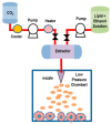
Schematic representation of the RESS method for liposome preparation. Initially, lipids are dissolved in supercritical CO2 and ethanol (5–10% of v/v) within an extractor. The resulting solution is depressurized through a heated nozzle in a low-pressure chamber. Finally, the formation of particles is generated, due to the supersaturation.
Figure 12
Figure 12
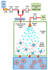
SuperLip method and mechanism of liposome formation. A high-pressure vessel is filled with an expanded liquid mixture (formed by PLs/ethanol/CO2 containing drugs). Water droplets are produced by atomization inside a high-pressure vessel. These droplets are rapidly surrounded by a lipid layer, forming a w/CO2 emulsion (inverted micelle). Finally, liposomes (w/w emulsion) are formed when they fall in the water pool located at the bottom of the vessel.
Figure 13
Figure 13
Schematic representation of the DELOS method. The lipids dissolved in organic solvent contained in a vessel at desired temperature and pressure, are mixed with SC-CO2 (used as a co-solvent to the organic solvent). Then, the mixture (depressurized at 35–55 bar) is expanded into CO2, and injected through a nozzle into in a vessel containing water bath and active drugs, where the liposomes are formed.
Figure 14
Figure 14
Schematic representation of a three-inlet microfluidic setup, (A). Confocal microscopy (false-color) pictures of the hydrodynamic focusing of an isopropyl alcohol (IPA) stream (that contains sulforhodamine (B) by two (aqueous buffer) streams, for 7 flow rate ratios (FRRs), increasing from 5 to 35 (increments of 5 from left to right) at a total constant volumetric flow rate VFR = 100 μL/min (B). Final liposome size distribution at different FRRs (C). Adapted with permission from Jahn et al. [129], Copyright 2007 American Chemical Society.
Figure 15
Figure 15
Schematic representation of the pulsed jet flow method. The lipids initially dissolved in the organic phase self-assemble (at the oil–water interface) as monolayers. The periodic pulses of a fluid jet (of a buffer) is directed at the interface of two nearby W/O microemulsions, and favors the formation of giant unilamellar vesicles [133].
Figure 16
Figure 16
Liposome formation process in the membrane contactor method.
Figure 17
Figure 17
X-ray diffraction patterns for the mixed lipid system composed of DMPC/ α-hydroxy-N-stearoyl phytosphingosine CER[AP] and of DMPC/N-stearoyl phytosphingosine CER[NP] multilamellar vesicles (MLVs) at the temperature of T = 30 °C Adapted by permission from Springer Nature: [156] (Appl. Phys. A) by Kiselev et al., Copyright 2013.
Figure 18
Figure 18
(A) Images of heparin-loaded liposomes (HLp), obtained by means of the SEM, TEM, and AFM techniques. (B) Confocal laser scanning microscopy images of cellular uptake of HLd (top) and the blank liposomes (BLp) (bottom) by fibroblast cell lines after 3 h of incubation. Blue (DAPI): nucleus; green (fluorescent HLp). Adapted with permission from Vaghasiya et al. [181], Copyright 2019 American Chemical Society.
Figure 19
Figure 19
Diagram indicating the electrical potential as a function of the ionic concentration (and distance from the charged surface) of a liposome suspended in a dispersion medium.

Similar articles

Cited by

References

    1. Bozzuto G., Molinari A.A. Liposomes as nanomedical devices. Int. J. Nanomed. 2015;10:975–999. doi: 10.2147/IJN.S68861. - DOI - PMC - PubMed
    1. Allen T.M., Cullis P.R. Liposomal drug delivery systems: From concept to clinical applications. Adv. Drug Deliver. Rev. 2013;65:36–48. doi: 10.1016/j.addr.2012.09.037. - DOI - PubMed
    1. Lombardo D., Calandra P., Barreca D., Magazù S., Kiselev M.A. Soft interaction in liposome nanocarriers for therapeutic drug delivery. Nanomaterials. 2016;6:125. doi: 10.3390/nano6070125. - DOI - PMC - PubMed
    1. Lee M.-K. Liposomes for Enhanced Bioavailability of Water-Insoluble Drugs: In Vivo Evidence and Recent Approaches. Pharmaceutics. 2020;12:264. doi: 10.3390/pharmaceutics12030264. - DOI - PMC - PubMed
    1. Ewert K.K., Scodeller P., Simón-Gracia L., Steffes V.M., Wonder E.A., Teesalu T., Safinya C.R. Cationic Liposomes as Vectors for Nucleic Acid and Hydrophobic Drug Therapeutics. Pharmaceutics. 2021;13:1365. doi: 10.3390/pharmaceutics13091365. - DOI - PMC - PubMed

LinkOut - more resources